Content last revised on September 15, 2026
SKKT106/14E Inspection and Official Specifications
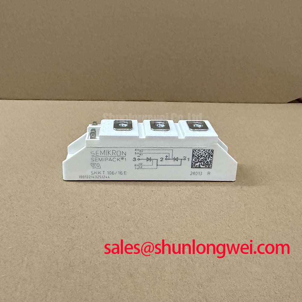
With the power source isolated, first verify the SKKT106/14E terminal arrangement against the equipment schematic and compare cold-state diode-mode readings across the corresponding main terminals before reconnecting any control or load wiring. This Semikron thyristor module has an official repetitive peak reverse and off-state voltage rating of 1400 V, an average on-state current rating of 106 A at Tc = 85°C, and an RMS on-state current rating of 180 A. These ratings establish the electrical boundary for evaluating a replacement in controlled rectifiers, DC supplies, and other line-commutated power assemblies.
The module should be assessed as a thyristor power component rather than as an IGBT switching device. Its gate terminals, anode connections, cathode connection, heatsink interface, protection network, and firing circuit must all correspond to the original equipment topology. The system integrator should verify the original circuit documentation before applying a gate trigger or a high-voltage test.
| Official Specification | Value | Engineering Relevance |
|---|---|---|
| Repetitive peak reverse and off-state voltage, VRRM / VDRM | 1400 V | Voltage withstand boundary during blocking and commutation states |
| Average on-state current, IT(AV) | 106 A at Tc = 85°C | Thermal current rating for the stated case-temperature condition |
| RMS on-state current, ITRMS | 180 A | RMS on-state current rating |
| Non-repetitive surge current, ITSM | 2250 A at Tvj = 25°C, 10 ms | Single surge withstand reference for protection coordination |
| Fusing value, I2t | 25,000 A2s at Tvj = 25°C | Reference for coordinating semiconductor protection devices |
| Maximum on-state voltage, VT | 1.65 V at IT = 300 A | On-state voltage limit at the stated test current |
| Junction-to-case thermal resistance, Rth(j-c) | 0.28 K/W per thyristor | Thermal path from one thyristor junction to the case |
SKKT106/14E Circuit Protection & Reliability: Calibrating Diode Peak Reverse Recovery Current
In an incoming inspection, begin by checking for case damage, terminal deformation, contamination on the mounting face, and mismatch between the installed wiring layout and the original converter drawing. A diode-mode test can help identify an unexpected low-resistance path or an open connection, but it is not a substitute for a controlled blocking-voltage or gate-trigger test. The expected forward-reading direction depends on the installed circuit arrangement, so comparison with a known-good assembly or the original terminal diagram is more useful than assigning a universal meter value.
The provided official specifications define the voltage, current, surge, forward-drop, and thermal limits of the SKKT106/14E. They do not establish an official diode reverse-recovery peak current, reverse-recovery time, or soft-recovery classification for a separate commutating diode. Those characteristics must be obtained from the documentation of the diode actually fitted in the converter. Treating a diode parameter as a property of this thyristor module would create an invalid basis for switch-loss or electromagnetic-interference assessment.
When a line-commutated rectifier shows abnormal commutation waveforms, inspect the diode path, transformer leakage behavior, gate-firing reference, and DC-bus transient response as a linked system. A high reverse-current peak or abrupt recovery waveform may indicate that the commutating diode and surrounding inductive path require evaluation with an isolated oscilloscope measurement. This is a Design Consideration, not an official SKKT106/14E recovery specification.
The official 25,000 A2s I2t rating at Tvj = 25°C supplies a defined reference for semiconductor-fuse coordination. Engineers should compare the prospective fault waveform, protective-device clearing behavior, and equipment protection study with the fuse documentation. The current rating alone does not prove that a selected fuse will protect every wiring fault, transformer fault, or commutation event.
The 2250 A non-repetitive 10 ms surge rating is also a fault-survival reference, not a normal operating current target. After any suspected short-circuit event, inspect the gate circuit and power terminals, then compare controlled low-energy measurements with records from a known functional channel where available. For product-family context, Semikron identifies the SEMIPACK thyristor and diode module platform within its power-module portfolio.
Bench Tip: Keep the module disconnected from energized capacitors and firing boards while taking cold-state readings, because stored system energy and parallel circuit paths can invalidate measurements and damage test equipment.
Benchtop Waveform Tuning: Mitigating Stress via Saturable Reactor and Snubber Sizing on SKKT106/14E
A snubber or saturable reactor must be evaluated from the complete converter waveform, not selected from the module current label alone. For the SKKT106/14E, the starting boundary is the official 1400 V VRRM / VDRM rating. Capture voltage at the device terminals using an appropriately rated differential probe, then evaluate the peak blocking voltage after commutation against the DC-link condition and the measured circuit transient. Probe grounding and lead routing must be controlled because measurement-loop pickup can make a benign waveform appear unstable.
RC snubber components can influence the rate of voltage rise seen across a blocking thyristor, while a series saturable reactor can shape current rise during applicable portions of the converter cycle. Their component values, dissipation capability, saturation behavior, and placement are system-determined. As an Engineering Recommendation, minimize parasitic loop inductance around the device, snubber, and commutation path to suppress inductive overshoot, then verify peak voltage and repetitive heating during switching tests.
Do not infer a universal snubber capacitance, resistor value, or reactor characteristic from the SKKT106/14E part number. The correct network depends on transformer impedance, line frequency, source inductance, load current, firing angle, wiring geometry, and the recovery behavior of any associated diode. A component change that reduces a measured voltage peak can also alter dissipated energy elsewhere in the circuit, so measurements should include the snubber temperature and the device terminal waveform.
Check terminal connections for secure electrical contact, correct conductor orientation, and strain-free routing before waveform tuning. The module mounting hardware and terminal fasteners should follow the applicable manufacturer mechanical documentation for the exact assembly. Installation torque is a Design Consideration unless specified in the official mechanical data for the installed module and hardware combination. Excessive force can distort the mounting interface, while insufficient force can increase connection resistance.
For an electrolyzer DC power rectifier, the SKKT106/14E can be evaluated as part of a controlled high-current rectifier section, subject to the original converter voltage, thermal design, firing circuit, and protection architecture. It should not be assumed to be a direct replacement merely because another module shares a similar voltage class. Where a higher-current module is being considered during a documented redesign, the SKKT 250/14E provides a separate product reference for objective comparison of electrical and mechanical requirements.
Transient Dynamics & Electrical Design: Non-Repetitive Surge On-State Current on SKKT106/14E
The SKKT106/14E official surge capability is 2250 A at Tvj = 25°C for 10 ms. This figure describes a non-repetitive on-state surge condition under the stated junction-temperature and duration conditions. It does not define repetitive overload capability, normal rectifier load current, or acceptable fault repetition. A measured current excursion must therefore be reviewed against the actual pulse duration, junction starting condition, protection-clearing behavior, and the original equipment design.
When investigating a suspected overload, record the available evidence before replacing components: protective-device condition, gate command timing, transformer secondary waveform, load condition, heatsink temperature, and visible terminal condition. A failed fuse, abnormal current waveform, or missing output voltage can arise from several causes. Use an isolated current probe and a known-good reference channel where practical rather than assigning the observation to a single device mechanism.
The IT(AV) rating of 106 A at Tc = 85°C and ITRMS rating of 180 A are separate official current definitions. Average current relates to the specified thermal operating condition, while RMS current reflects heating from the waveform. A rectifier load with ripple, phase imbalance, or abnormal firing can change both stresses. The system engineer should calculate and measure the actual current distribution for the installed topology before deciding whether operating behavior remains within the equipment design envelope.
Before reverse voltage is reapplied following an abnormal surge event, verify that the protection path has cleared the fault and that the device is not being exposed to an uncontrolled re-energization sequence. Controlled checks should include terminal isolation, gate-circuit integrity, and blocking behavior using equipment suitable for the required voltage class. No field-life, failure-rate, altitude, EMC, safety-certification, or insulation-reliability claim is implied by the surge specification alone.
The relationship between conventional thyristor modules and newer power-semiconductor approaches can be reviewed in the Wide Bandgap Revolution technical article. That discussion is useful for broader technology evaluation, while SKKT106/14E integration should remain governed by its own official ratings and the original converter requirements.
Benchtop Waveform Tuning: Mitigating Stress via Ensuring Uniform Heatsink Contact Pressure on SKKT106/14E
Before applying thermal compound, clean the SKKT106/14E mounting face and the heatsink contact area with a material compatible with the equipment maintenance procedure. Inspect for particles, scratches, corrosion residue, and localized high spots. A clean, flat contact interface supports repeatable heat transfer and makes later temperature comparisons more meaningful. Spread thermal interface material as a thin, continuous layer suitable for the established service process, avoiding voids and excess material at the edges.
The official junction-to-case thermal resistance is 0.28 K/W per thyristor. This value describes the internal junction-to-case thermal path under the manufacturer test conditions. It does not include heatsink thermal resistance, interface material, airflow, cabinet temperature, conductor losses, or the distribution of heat within the full power assembly. The final case-to-ambient performance must therefore be verified in the actual enclosure.
Apply mounting force in a balanced sequence so contact pressure develops uniformly across the module base. The correct torque and tightening procedure must be confirmed from the relevant manufacturer mechanical information and the equipment hardware specification. This approach helps avoid a tilted mounting plane, uneven interface material displacement, and uncertainty in the thermal path. After installation, verify that busbars and control wiring do not impose mechanical stress on the module terminals.
During controlled commissioning, monitor case temperature at repeatable locations and compare the waveform, load current, and thermal behavior with the original service baseline. A temperature rise that differs from the expected equipment trend may indicate a heatsink-interface issue, uneven current sharing, altered firing behavior, cooling degradation, or another system-level condition. Inspecting the device in context provides a more defensible result than attributing thermal behavior to one parameter alone.