

Content last revised on November 13, 2026
Transient Dynamics & Electrical Design: Managing Commutation Stress on SKKD100/16
With the equipment isolated and stored energy discharged, trace the SKKD100/16 power terminals against the rectifier schematic before reconnecting busbars. The important distinction is electrical: SKKD identifies a diode module, so thyristor gate checks and firing-angle settings do not belong to this component. Establishing that distinction first prevents a rectifier repair from becoming an unnecessary investigation of the firing controller.
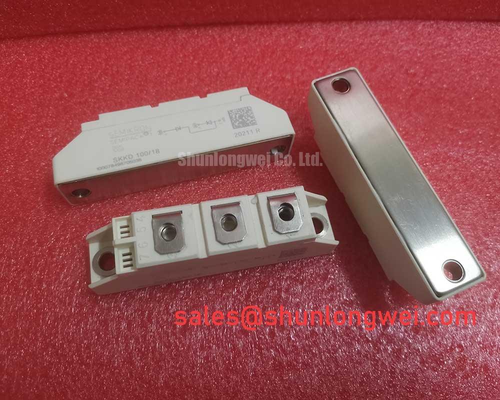
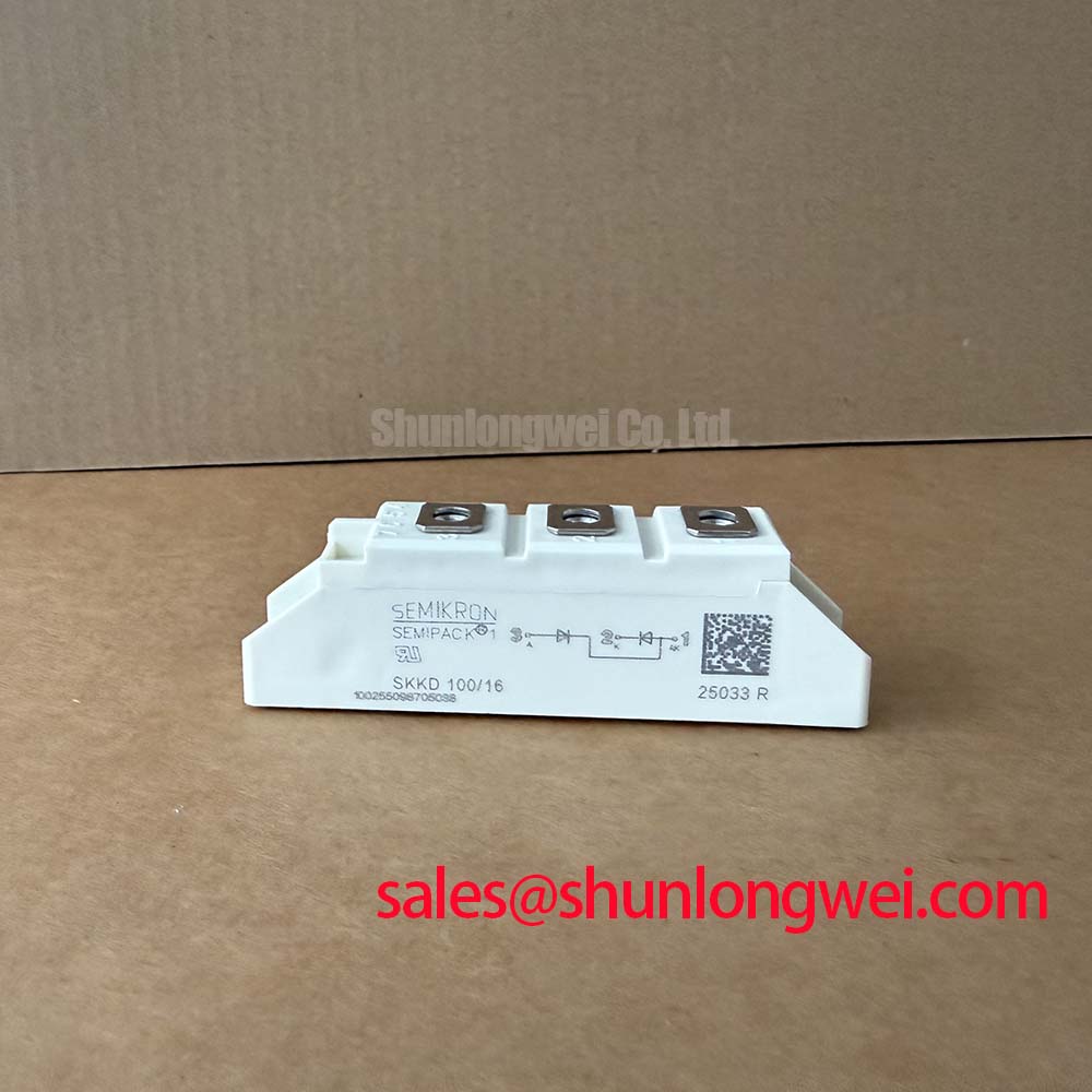
The Manufacturer is Semikron, and the Part Number is SKKD100/16. Its primary ratings are Repetitive Peak Reverse Voltage (VRRM): 1600.0 V and Average Forward Current (IF(AV)): 100.0 A. The average-current rating applies under the conditions specified in the device datasheet, not as an unconditional operating limit. The Package: SEMIPACK and the device type is Diode Module, within the broader SEMIPACK thyristor/diode module family.
Exclude gate hotspot burnout from the SKKD100/16 diagnostic path: its diode function has no gate firing pulse, gate trigger current, or back-porch holding requirement. Those checks apply to thyristors elsewhere in a controlled converter. A steep gate pulse or repeated firing sequence cannot correct an open diode path, a loose power connection, or inadequate heat removal.
Design Consideration: investigate transient stress at the module’s power terminals instead. Reverse recovery and circuit inductance can produce voltage excursions during commutation. When the equipment uses an RC snubber, inspect its capacitor, resistor, connections, and physical loop against the original schematic. Component selection depends on measured ringing, repetitive dissipation, and the converter’s operating conditions, rather than the module’s voltage rating alone.
Capture the voltage waveform using appropriately rated differential measurement equipment and a connection arrangement that limits measurement-loop pickup. Compare behavior under equivalent load conditions before attributing ringing to the semiconductor. An intermittent terminal connection, altered busbar routing, or disconnected suppression component can change the observed waveform without identifying a single definitive failure cause.
The Semikron SEMIPACK® Thyristor / Diode Modules family reference provides the manufacturer’s product context. For protection coordination, use the exact device’s surge-current and I²t limits alongside the fuse manufacturer’s clearing characteristics; do not derive fuse suitability from the average-current rating.
Assembly Integrity & Layout Architecture: Integrating SKKD100/16 in Rectifier Circuits
Locate the controlled devices in the schematic before changing any firing-delay setting, because the SKKD100/16 itself cannot adjust firing angle. In a converter containing both diodes and thyristors, the controller acts on the thyristors; diode conduction follows circuit voltage and current conditions. The relationship between firing angle, DC output, power factor, and reactive demand depends on the complete bridge and load.
Design Consideration: when evaluating an induction melting or hardening furnace power supply, first identify whether this module occupies an input rectifier position or another documented diode position. Compatibility assessment should include conduction duty and commutation requirements. A rectifier module’s blocking-voltage rating does not establish suitability for a high-frequency inverter position.
Keep cross-model assessment separate from mechanical resemblance. The SKKT500-16E is a comparison candidate for a different controlled-device requirement, not an automatic substitute. A thyristor circuit introduces gate-drive and control requirements that a diode circuit does not have.
| Selection check | SKKD100/16 | SKKT500-16E |
|---|---|---|
| Device distinction | Diode module | Thyristor module; not a direct functional replacement |
| Repetitive peak reverse voltage | 1600.0 V | Consult datasheet |
| Average forward current | 100.0 A under specified datasheet conditions | Consult datasheet for applicable current rating and conditions |
| Housing and installation | SEMIPACK; match terminal drawing and mounting requirements | Consult datasheet for dimensions, terminals, and tightening torque |
At assembly, support the conductors so their weight does not preload the module terminals. Use the applicable mounting and terminal torque instructions rather than treating housing-family resemblance as a torque specification. Preserve the equipment’s documented creepage and clearance paths, including around lug edges, washers, and insulating barriers. Remove conductive debris and address condensation before energization; no universal spacing value follows from the module’s blocking-voltage rating.
Field Diagnostics & Commissioning: Surge and Thermal Limits in SKKD100/16 Circuits
Evaluate surge events against the device’s non-repetitive surge conditions, not an assumed avalanche capability. A sinusoidal half-cycle surge rating is meaningful only with its stated duration, initial junction temperature, and subsequent voltage conditions. For this diode module, use diode-specific surge notation and limits rather than transferring thyristor I_TSM figures from another component.
Design Consideration: assess pulse heating using the applicable transient thermal impedance information and the actual current waveform. Starting case temperature, pulse repetition, and cooling between events affect peak junction temperature. Reverse-voltage reapplication must remain within the documented operating conditions; surviving an isolated current pulse does not establish repetitive surge capability.
Inspect the thermal path during planned shutdowns: clear heatsink passages, check fan operation, and examine the mounting interface for disturbed contact or degraded thermal material. Set inspection intervals from equipment duty, contamination, and temperature trends rather than assigning an unsupported universal service period. The From Chip to Air Technical Reference offers supporting thermal-path principles, while device-specific limits remain those of the SKKD100/16 documentation.
Maintenance Note: Trend terminal and heatsink temperatures under comparable loads, and check airflow before returning a repeatedly overheating assembly to service.
During recommissioning, compare current balance, terminal temperature rise, and rectified output with the equipment’s accepted baseline. Investigate deviations alongside cooling condition, connection integrity, and upstream protection behavior before increasing load.