Content last revised on September 21, 2026
Assembly Integrity & Layout Architecture: Implementing Power Factor Degradation and Harmonic Mitigation for SKKT107/16E
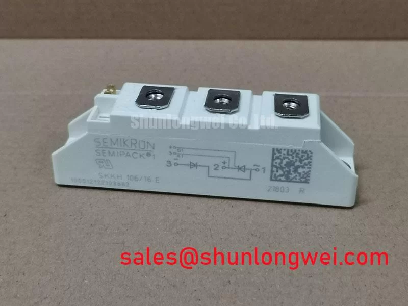
With the isolated starter cabinet de-energized, first inspect the SKKT107/16E Semipack housing, power terminals, mounting faces, and connected gate leads for looseness, heat discoloration, cracked insulation, or contamination before attempting any electrical check. A cold multimeter check can identify an obvious shorted power path or a damaged gate connection, but it cannot confirm dynamic blocking capability, trigger sensitivity, commutation behavior, or surge endurance under operating voltage.
The SKKT107/16E is a Semikron thyristor module supplied in the Semipack package. Its published factory ratings include a 1600 V voltage rating and a 107 A current rating under specified conditions. These are Official Datasheet Specifications and must be verified against the equipment’s original circuit position, line conditions, thermal assembly, gate-control board, and protection network before replacement or recommissioning.
| Identification Item | Official Specification |
|---|---|
| Manufacturer | Semikron |
| Module Model | SKKT107/16E |
| Voltage Rating | 1600 V |
| Current Rating | 107 A |
| Package | Semipack |
| Product Family Context | Thyristor module technology |
For a high-voltage three-phase motor solid-state soft starter, begin by confirming that the replacement module’s terminal arrangement matches the removed device and the controller wiring diagram. Do not infer terminal identity from enclosure orientation alone. The 1600 V rating is an Official Datasheet Specification for the module, not a statement that any particular three-phase line voltage, surge environment, or control topology is automatically suitable.
In phase-angle motor control, moving the firing point from an early angle toward a delayed angle reduces the portion of each AC waveform delivered to the motor. Across a firing-angle range from 0 degrees through 150 degrees, the motor voltage transfer and torque response are determined by the complete starter arrangement, including motor characteristics, phase balance, trigger timing, supply impedance, and bypass strategy. Delayed firing can increase reactive power demand and harmonic current content. This is a Design Consideration for the soft-starter system, rather than a module-specific guarantee.
Inspect busbar flatness, terminal contact surfaces, insulating barriers, and the heat-transfer interface before installation. A distorted busbar or uneven clamping plane can create localized resistance and uneven thermal loading even where the module remains electrically functional. The original equipment documentation must govern mounting hardware, terminal torque, fuse coordination, and semiconductor protection settings because no mounting torque, fuse I²t, surge-current, or thermal-resistance values are established by the listed factory data here.
⚠️ Field Alert: Tighten electrical and mounting hardware only to the torque specified by the original equipment documentation, using clean contact faces and an even, thin thermal interface layer.
For engineers comparing power-module families during an equipment assessment, SKKT500/08E is a separate Semikron reference model that should be evaluated only by its own official voltage, current, package, terminal, and thermal specifications. Similar naming or product-family membership does not establish direct interchangeability.
Semikron’s SEMIPACK® thyristor and diode module information provides useful family-level context when checking package construction and application categories. Final replacement approval remains dependent on the original starter schematic and documented module connection map.
Benchtop Waveform Tuning: Mitigating Stress via Gate Trigger Current Dynamics on SKKT107/16E
Before applying line power, verify gate-circuit continuity from the control board connector to the module terminals and compare all three phase channels against the known wiring arrangement. A damaged gate lead, weak connector contact, incorrect polarity, or unequal trigger path can produce erratic conduction that resembles a power-stage failure. Scope verification should be performed with safe isolation practices and a measurement method suitable for the voltage environment.
Gate trigger current, gate trigger voltage, holding current, latching current, permissible gate pulse conditions, and gate rise-time limits are not included in the provided factory parameter set for SKKT107/16E. Therefore, no numerical gate-drive prescription should be assigned to this model from this page. The system integrator should verify these limits from the original Semikron datasheet and the existing trigger-board documentation.
A Design Consideration is to compare the timing and shape of trigger pulses across all controlled paths under controlled test conditions. Where the starter controller uses repeated gate pulses, the pulse train must be evaluated as part of the controller design, including its firing-angle command, synchronization reference, load current, and expected commutation conditions. A sustained or poorly timed gate command can create abnormal behavior, while a missing pulse can prevent the intended phase from conducting. Neither condition should be diagnosed from gate resistance alone.
When an oscilloscope reveals unequal phase behavior, inspect the reference return path, connector retention, controller synchronization, and the power-side waveform together. A waveform difference may indicate a trigger-path issue, load imbalance, snubber interaction, or an existing power-device defect. It should be confirmed against the original equipment’s known-good measurement path rather than assigned to one cause.
Resources discussing Evolution of Negative Off-Bias Gate Drive Circuits can assist engineers reviewing gated semiconductor control concepts. Their applicability must be confirmed for the installed thyristor control architecture; they are not a substitute for the SKKT107/16E gate specifications.
SKKT107/16E Circuit Protection & Reliability: Calibrating Thermal Duty Cycle Management of Bypass Control
In a three-phase motor soft starter, the semiconductor stage commonly carries controlled current during acceleration while the wider system may use a bypass contactor after the motor reaches its intended operating condition. The exact bypass sequence, current threshold, acceleration duration, and contactor interlocking logic are system-determined. They must not be derived from the module’s 1600 V and 107 A ratings alone.
Motor locked-rotor current can be several times the motor nameplate current, and phase-angle control is often used to reduce mechanical shock during startup. The achievable current reduction depends on motor design, driven load inertia, supply conditions, firing program, and feedback logic. It is a Design Consideration to validate the complete start sequence by recording phase current, line voltage, module temperature behavior, and bypass transfer timing during a controlled commissioning test.
Thermal duty cannot be assessed solely from average current. Repeated starts, incomplete acceleration, stalled loads, uneven phase conduction, poor heatsink contact, and delayed bypass operation can all increase semiconductor stress. The provided data does not establish an allowable number of starts, service-life duration, overload factor, junction-temperature excursion, or field failure rate. Maintenance decisions should therefore rely on the original starter documentation, measured operating conditions, and the module’s complete manufacturer datasheet.
Protection review should include the upstream fuse type, fuse coordination evidence, enclosure airflow, heatsink cleanliness, contactor condition, and controller fault response. Semiconductor fuse I²t coordination must be calculated or selected from documented fuse and module data, not estimated from nominal current rating. If the application contains a freewheel or commutation diode path, diode reverse-recovery behavior can affect transient current and conducted noise. Semikron’s CAL diode technology information is relevant technology background, but it does not confirm the internal diode construction or recovery characteristics of this specific module.
Preventing Spurious Faults: Critical Rate of Rise of Off-State Voltage Guidelines for SKKT107/16E
Unexpected firing or abnormal phase conduction should prompt an inspection of the complete protection path before the module is condemned. Check the RC snubber components for physical damage, connection integrity, capacitor degradation, resistor overheating, and correct placement across the intended circuit nodes. Inspect metal-oxide varistor protection for cracking, discoloration, or evidence of surge exposure, while recognizing that visual inspection alone cannot establish clamping performance.
An RC snubber and a MOV perform different jobs in an industrial starter. The snubber can control transient voltage shape and damp circuit ringing, while a MOV can limit larger overvoltage events within the protection design. Their component values, energy ratings, placement, and coordination must be determined from the supply environment, motor cable arrangement, measured switching waveform, and original design documentation. No RC or MOV values are Official Datasheet Specifications for SKKT107/16E based on the available parameter set.
Series inductive elements, including saturable reactors where used by the starter design, can influence current rise and transient behavior. Their selection is a system-level Design Consideration requiring validation against measured current waveform, line impedance, motor characteristics, and protective-device coordination. Avoid changing these parts simply to remove a nuisance trip, because the apparent fault can originate in timing, load conditions, line disturbances, bypass transfer, or a degraded protection component.
During recommissioning, verify that off-state voltage stress remains within the module’s documented limits and that the measured peak condition is assessed against the 1600 V Official Datasheet Specification. Use appropriately rated probes and controlled procedures. Where waveform anomalies persist, compare each phase path with the original schematic and a verified healthy channel before returning the soft starter to service.