Content last revised on October 14, 2026
Preventing Spurious Faults: Current-Limit Mode vs Linear Voltage Ramp Guidelines for SKKD101-16
I compare the controller’s current trace with its commanded ramp before treating a starting fault as a failed SKKD101-16. As a Design Consideration, a voltage ramp and a current-limited start regulate different quantities: increasing applied voltage does not establish a predictable current ceiling, while current limiting can restrict acceleration when the available motor torque is insufficient. The operating settings belong to the motor, load, controller, and protection coordination, not to this diode module.
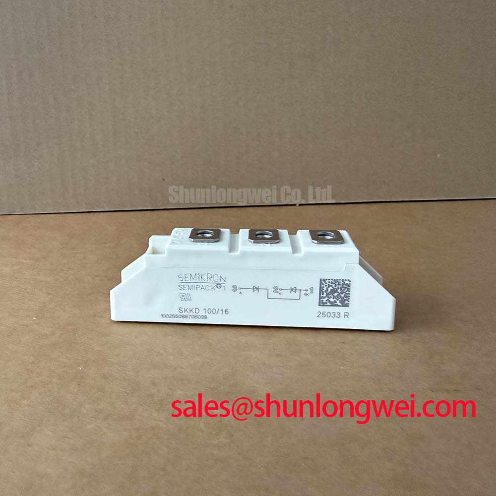
The distinction matters because SKKD101-16 is a diode module, not a gate-controlled soft-start switch. It cannot independently regulate phase angle, accept a negative gate bias, or implement a starting-current command. When evaluating a high-voltage three-phase motor solid-state soft starter, identify the module’s actual position in the equipment schematic before assessing compatibility. A rectifier position and a controlled switching position impose different terminal functions and operating stresses.
For cold checks, disconnect parallel paths where practical and compare diode-mode readings in both directions across the documented terminal pairs. Capacitors, snubbers, and connected semiconductor branches can alter an in-circuit reading. A repeatable difference from the equivalent healthy branch warrants further isolation; a meter result alone does not establish the module’s full-load condition.
As an Engineering Recommendation, review the installed fuse’s total clearing I²t against the semiconductor’s applicable withstand data at the specified temperature and fault conditions. Also check terminal identification, conductor seating, and the manufacturer’s separate tightening requirements for electrical connections and heatsink attachment. The Semikron SEMIPACK thyristor and diode module range provides relevant product-family context, but the exact device documentation governs the installation.
Preventing Spurious Faults: Minimizing Commutation Turn-Off Voltage Spikes: Guidelines for SKKD101-16
Capture the voltage across the commutating diode with an appropriately rated differential measurement arrangement, then correlate the transient with branch current and the equipment’s fault record. As a Design Consideration, diode reverse recovery and circuit inductance can contribute to voltage overshoot when current transfers between branches. Probe placement and measurement-loop pickup must be checked before interpreting ringing as a device problem.
Reverse-recovery peak current and recovery time are meaningful only with their associated forward current, current-change rate, reverse voltage, and junction-temperature conditions. Do not assign a soft-recovery characteristic to SKKD101-16 from a general technology description. The manufacturer’s CAL diode technology information is useful background, not evidence that this particular module uses CAL technology or carries its published recovery characteristics.
As an Engineering Recommendation, preserve the intended current-return geometry and inspect disturbed busbar joints before modifying suppression components. The system engineer should establish acceptable transient margins through measurements under representative operating conditions. The linked IGBT Design & Integration reference offers surrounding converter integration context; its gate-drive guidance applies to controlled switches, not to the diode terminals of this module.
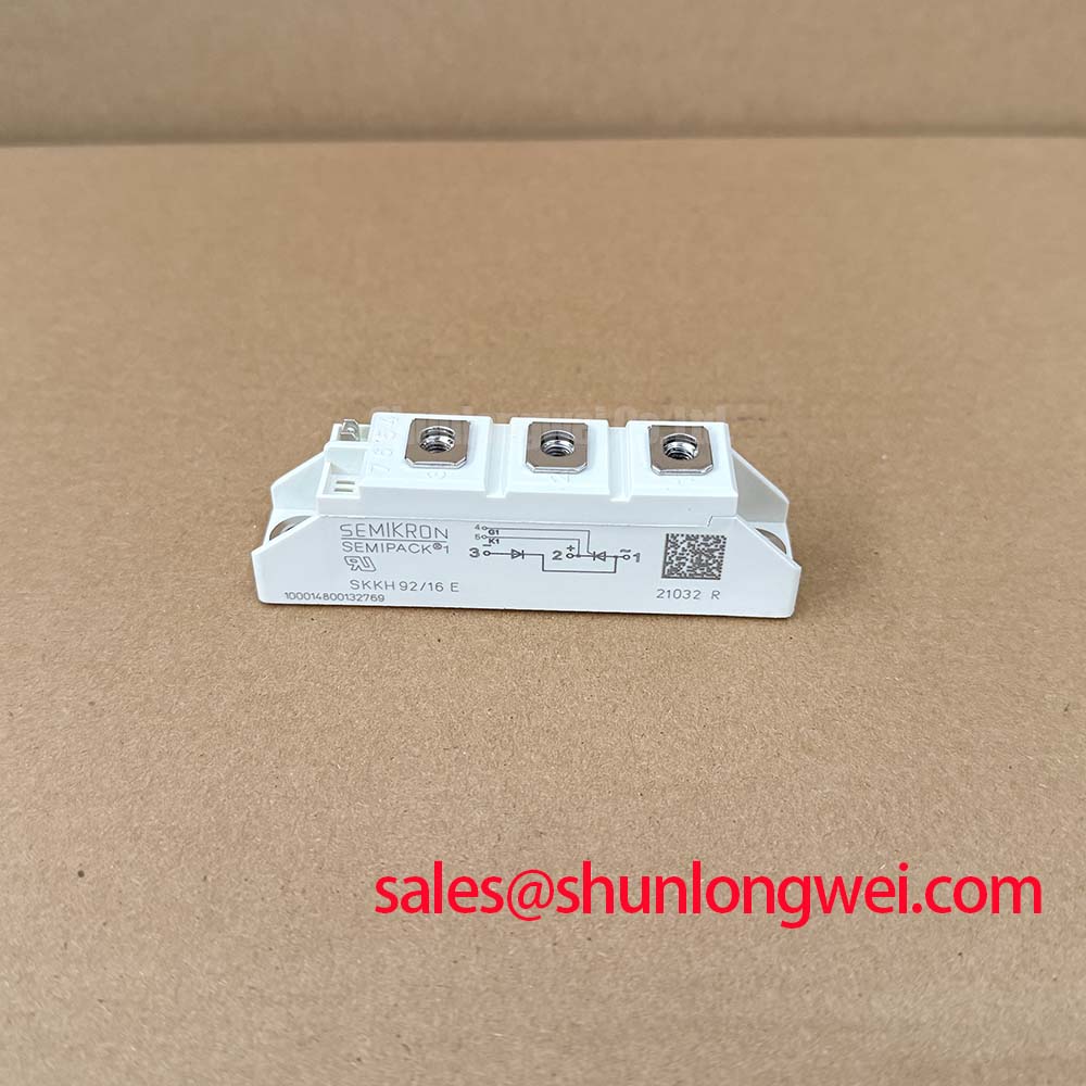
A replacement comparison with SKKH 162/16E must account for its thyristor/diode configuration. It is not an established direct replacement for SKKD101-16. Matching a housing family or voltage designation does not establish matching internal connections, gate requirements, current capability, or protection coordination. Resolve those differences against the equipment circuit before considering any substitution.
Preventing Spurious Faults: Thermal Interface Material Spreading across Guidelines for SKKD101-16
Inspect the heatsink contact surface and the removed interface-material pattern before cleaning away evidence of uneven seating. As a Design Consideration, incomplete contact, contamination, or assembly distortion can increase the thermal resistance between the module and heatsink. Junction-to-case thermal resistance describes a different part of the heat path and should not be used as a substitute for evaluating the mounting interface.
Check the mounting surface for damage and confirm that the module seats without being pulled into alignment by its fasteners. Apply the interface material using the approved assembly method, maintaining even coverage without prescribing an unsupported layer thickness. Use the module-specific mounting sequence and torque requirements, keeping them distinct from power-terminal tightening instructions.
Field Alert: Do not use terminal bolts to force a misaligned busbar into position; correct the mechanical fit before tightening the electrical connection.
During the return-to-service check, compare case-temperature behavior between equivalent branches under comparable loading and cooling conditions. Investigate differences alongside airflow, heatsink cleanliness, connection condition, and current sharing rather than assigning a single cause. Keep conductive residue away from terminal insulation surfaces, restore the original barriers, and verify the equipment’s required clearances after assembly. Acceptance should follow the equipment’s electrical and thermal test procedure, with measured operating conditions recorded for the repair handover.