Content last revised on October 5, 2026
SKKH75-16E Circuit Protection and Post-Surge Blocking Checks
Isolate the power stage, discharge the DC link, and compare the cold terminal paths of the removed SKKH75-16E with the equipment schematic before reconnecting any gate wiring. A meter check can reveal a hard short or an open connection, but it cannot establish the module’s blocking capability under operating voltage. Record the terminal markings and the position of every cable before removal.
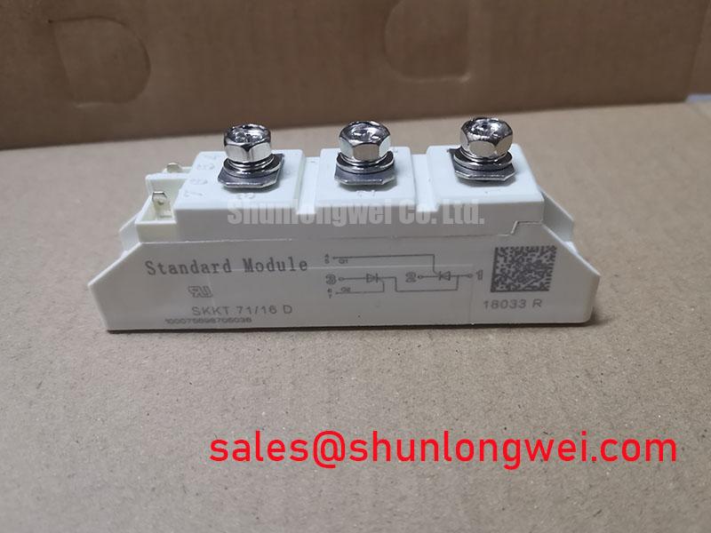
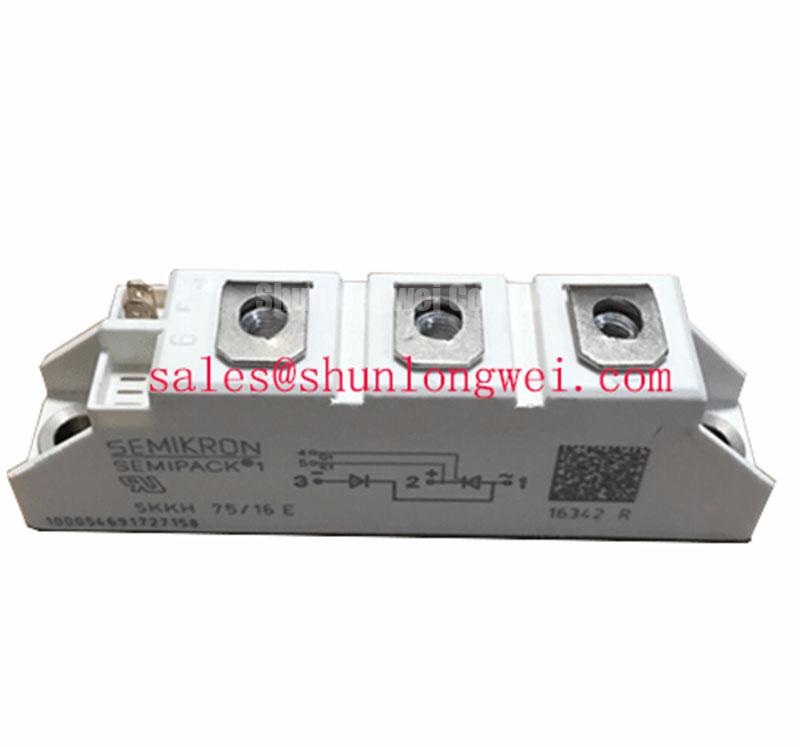
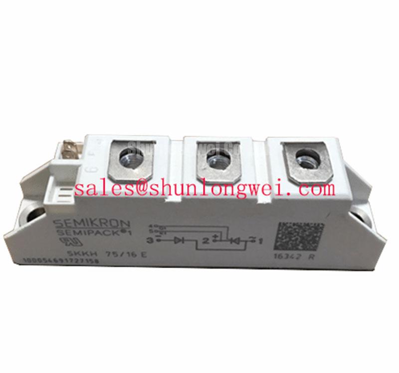
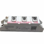
The SKKH75-16E is a Semikron Semipack thyristor/diode module. For a replacement assessment, the required blocking voltage, operating current, surge duty and terminal configuration must agree with the exact manufacturer datasheet and the equipment design. A purchasing record supplied for this part lists voltage and current figures, but those figures should not be treated as verified factory ratings or used to size protection without checking the exact part documentation. This distinction matters when returning a rectifier to service after a fuse operation or an unexplained trip.
Design Consideration: A cold resistance check is an initial screen, not a reverse-blocking test. Compare readings across the main terminals with an established reference procedure, then inspect the associated fuse, bus connections and trigger circuit for evidence of the same event. A low reading may reflect an external parallel path unless the module has been electrically isolated. Conversely, a plausible meter reading does not rule out a fault that appears only with applied voltage or temperature.
For surge assessment, obtain the manufacturer’s conditions for the sinusoidal 10 ms half-cycle surge rating and its fuse coordination data before comparing the protection device’s let-through energy with the module limit. The permitted surge depends on the stated initial junction temperature and on whether reverse voltage is reapplied after the pulse; neither condition can be inferred from the part number. Check the fuse’s published operating characteristics against the actual prospective fault current, rather than treating a current rating alone as protection coordination.
The manufacturer’s SEMIPACK thyristor and diode module information provides product-line context. It does not replace the exact SKKH75-16E datasheet when a repair decision depends on a surge limit, blocking rating or terminal assignment.
Mounting Contact, Thermal Path and Terminal Integrity
Remove old interface material from the heatsink and inspect its seating surface before placing the replacement module. Dirt, raised burrs or an uneven surface can prevent consistent contact across the baseplate. Apply the thermal interface material in accordance with the module and heatsink instructions, seat the package without rocking it, and tighten its mounting fasteners in the specified sequence. Verify the mounting torque in N·m from the applicable manufacturer document; a general bolt torque is not a substitute for a module-specific limit.
Field Alert: Do not use the power terminals to pull a poorly seated module flat against the heatsink.
Design Consideration: The junction-to-case thermal resistance describes one part of the heat path, not the complete path into the cabinet cooling system. To assess temperature margin, verify the factory Rth(j-c) value for the exact module, then account for interface contact, heatsink performance, airflow and the equipment’s operating duty. A fresh application of paste cannot compensate for distorted mounting surfaces or restricted cooling.
Check each terminal connection against the circuit drawing before energizing. Cable lugs should sit flat, with conductors supported so that cable weight does not load the module terminals. Compare gate and auxiliary connections with the original wiring record, not with the apparent direction of nearby busbars. If the repair involves vibration or repeated heating cycles, inspect the wider assembly for loosened supports and cable movement; determine any corrective restraint from the equipment’s mechanical design.
Turn-On Current Rise and Snubber Verification
A thyristor/diode module cannot be assessed in isolation from its trigger circuit and commutation path. Before changing components around the SKKH75-16E, trace the installed RC snubber, gate wiring and any series reactor against the original schematic. Inspect snubber components for damage and confirm their connections. A missing or altered snubber may change transient voltage at the module, while an unsuitable trigger path can affect turn-on behavior. Neither symptom identifies a single failed component without measurement.
Design Consideration: Snubber resistance and capacitance should be evaluated against measured switching transients, device limits and the actual circuit topology. A series saturable reactor, where present, may help limit the initial current rise, but its suitability depends on the equipment’s commutation conditions. Do not transfer component values from a different rectifier merely because its module uses a similar package. During controlled testing, capture terminal voltage and current waveforms and verify that measured peaks remain within confirmed manufacturer limits.
If another catalog part is being considered, SKKD162/12 is a separate module to compare by topology, ratings, terminal layout and mounting interface; it is not an assumed drop-in replacement for SKKH75-16E. The same discipline applies when evaluating a different semiconductor technology: the Wide Bandgap Revolution discussion offers broader device-technology context, while allowable margins for this repair still come from the installed circuit and the exact module specifications. Semikron’s bare-die technology information likewise should not be read as a claim that a particular diode technology is present inside this module.
Firing-Angle Checks in a Controlled Rectifier
Where the SKKH75-16E is used in a controlled rectifier, check the trigger sequence before attributing poor DC output to the module. Compare the firing command with the relevant AC phase reference and observe the rectified output under a permitted test condition. As firing is delayed, average DC output and the supply-side current waveform change; the effect on power factor and reactive demand belongs to the complete converter and its load, not to a standalone module specification.
Design Consideration: For an induction melting or hardening furnace rectifier, compatibility depends on the existing power-stage topology, cooling arrangement, protection coordination and gate-drive connections. If power factor has deteriorated after a repair, compare phase voltages, firing signals and measured current with the equipment’s established commissioning records. An unbalanced supply, incorrect trigger timing or a load-side change can produce overlapping symptoms. Harmonic mitigation and any firing-angle limits must therefore be determined and validated at system level.
Before returning the equipment to duty, document the terminal mapping, mounting checks, fuse identification and controlled-test waveforms alongside the verified SKKH75-16E datasheet revision. If the required voltage, current, surge or thermal ratings remain unresolved, keep the replacement assessment open rather than using the unverified purchasing figures as an operating boundary.