

Content last revised on September 16, 2026
Field Diagnostics & Commissioning: Minimizing Commutation Turn Off Voltage Spikes in SKKH570/16E Topologies
The official repetitive voltage rating is VRRM / VDRM = 1600 V. Its official average on state or forward current rating is IT(AV) / IF(AV) = 570 A at Tc = 85 °C, while the stated RMS current capability is ITRMS = 1000 A. These values define the module’s electrical boundary; they do not by themselves confirm suitability for a particular commutation network, transformer arrangement, or operating waveform.
During a field inspection, record the existing terminal arrangement before disconnecting conductors. Check the main power terminals for discoloration, looseness, cracked insulation, and signs of localized heating. A cold resistance comparison between corresponding power paths can identify a clear imbalance, but a multimeter reading should not be treated as a complete semiconductor health test. Compare the suspect path with a known good module or the original circuit documentation, then confirm abnormal behavior using controlled voltage and current measurements.
Commutation turn off stress is affected by circuit inductance, current transfer, reverse recovery behavior, and the external protection network. The supplied factory data does not provide reverse recovery current Irrm or recovery time trr for this product page. Designers should therefore verify those values from the applicable Semikron documentation before calculating switching loss, electromagnetic interference behavior, or snubber requirements. The manufacturer’s SEMIPACK thyristor and diode module documentation is the appropriate technical reference for the product family.
Field Alert: Isolate and discharge the complete power stage before removing terminals, and follow the original assembly drawing for conductor order and mechanical fastening.
Benchtop Waveform Tuning: Mitigating Stress via Dynamic Voltage Sharing and RC Damping on SKKH570/16E
Bench testing should begin with the factory voltage and temperature boundaries clearly identified. The specified virtual junction temperature range is Tvj = −40 °C to 125 °C, and the specified thyristor junction to case thermal resistance is Rth(j-c) = 0.055 °C/W. These are official specifications for thermal evaluation, not a complete prediction of case temperature, heatsink temperature, or transient junction temperature in the finished equipment.
RC damping and any series reactor must be selected from measured circuit behavior. A Design Consideration is to minimize the parasitic commutation loop and observe the voltage across the module during turn off, voltage reapplication, and abnormal load transitions. The system engineer should select resistor and capacitor values only after checking the measured peak voltage, repetitive pulse energy, capacitor technology, resistor pulse capability, and the resulting thermal load. The SKKH570/16E datasheet information supplied here does not specify a universal Rs or Cs combination.
Use a properly rated differential probe and verify probe placement at the module terminals rather than at a distant control board connection. Gate wiring should be kept separate from high current paths, with the return route arranged according to the original circuit topology. For isolated driver boards, designers should evaluate optocoupler or digital isolator common mode transient performance against the measured switching environment. This product page does not establish a CMTI rating for any external driver or control circuit.
Dynamic voltage sharing is a system-level result. If parallel or series paths are present, confirm component matching, layout symmetry, gate drive timing, and protection coordination during controlled tests. Do not infer equal voltage distribution from physical symmetry alone.
SKKH570/16E Circuit Protection & Reliability: Calibrating Non Repetitive Surge On State Current
The official non repetitive surge current specification is ITSM = 15,500 A for a 10 ms half sine wave at Tvj = 125 °C. This is a defined surge test condition, not a continuous operating rating and not permission to expose the module to repeated fault pulses. The normal current ratings remain 570 A average and 1000 A RMS under the stated conditions.
For a failed fuse or short circuit event, inspect the fuse class, clearing behavior, prospective fault current, and the manufacturer’s coordination data for the complete assembly. No fuse I2t coordination value has been provided in the supplied product parameters, so the protection device must be verified against the applicable Semikron fuse coordination table rather than selected from the module’s ITSM value alone.
Before reapplying reverse voltage after a surge event, inspect the module, heatsink interface, bus connections, and gate circuit. Check for changed cold impedance, visible package damage, loosened terminals, and insulation degradation. Thermal calculations should account for the measured case temperature, the specified 0.055 °C/W junction to case resistance, pulse duration, and the transient thermal impedance information from the complete datasheet. A single static resistance test cannot establish safe high voltage operation.
For a broader inspection sequence covering power semiconductor measurements and failure analysis, consult the Field Engineer’s Handbook. When comparing possible circuit configurations, the SKKT91/08D is a separate Semikron thyristor module and must be checked independently for voltage, current, package, terminal, and gate drive compatibility.
SKKH570/16E Operational Boundaries: Evaluating AC Line Surge Immunity and Lightning Transient Limits
The 1600 V VRRM / VDRM rating defines the module’s repetitive reverse and off state voltage boundary under its specified test conditions. It does not represent an independent lightning surge certification or prove compliance of the assembled furnace power supply with an EMC or immunity standard. AC input protection should be evaluated at the equipment level, with the line system, transformer, protective earth, enclosure, and upstream protection all included in the test arrangement.
A Design Consideration for an induction melting or hardening power supply is to coordinate the MOV, fuse, RC network, wiring inductance, and semiconductor voltage rating as one protection system. The system designer should verify MOV clamping voltage, energy capability, leakage behavior, thermal placement, and failure containment against the actual line conditions. IEC 61000-4-5 testing, where applicable to the finished equipment, must be performed on the complete system; the SKKH570/16E itself should not be described as independently EMC certified.
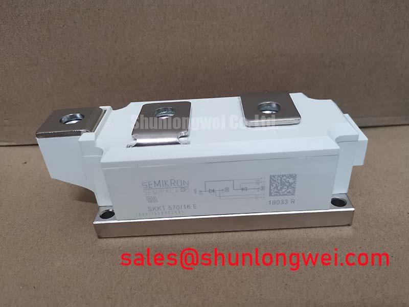
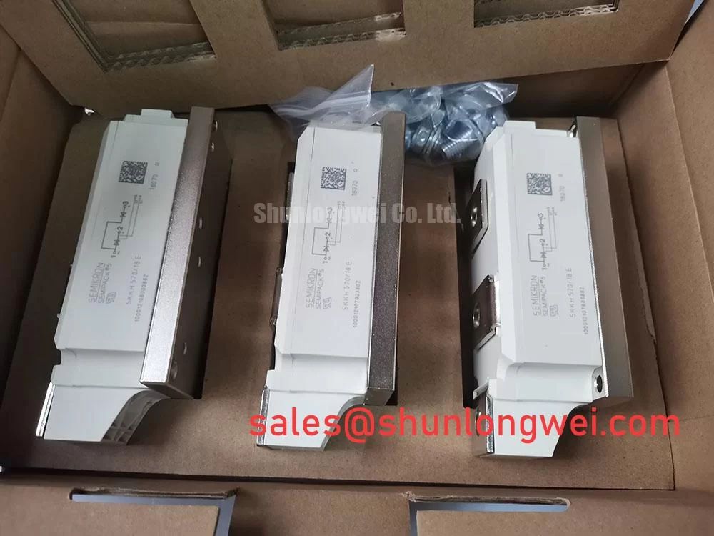
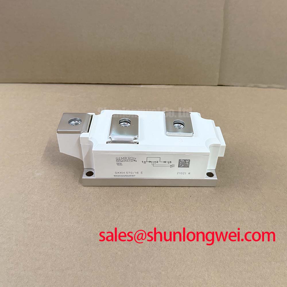
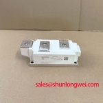
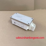
The SEMIPACK 5 housing is specified at 150 × 60 × 52 mm. Confirm the mechanical envelope, terminal spacing, heatsink flatness, insulation clearances, and airflow before installation. The module’s specified junction temperature range of −40 °C to 125 °C still requires the equipment designer to establish case temperature under the actual duty cycle. After commissioning, capture startup, steady state, current transfer, and abnormal interruption waveforms so that voltage peaks can be checked against the documented device limits.