Content last revised on September 17, 2026
SKKT500/18E Incoming Inspection and Electrical Verification
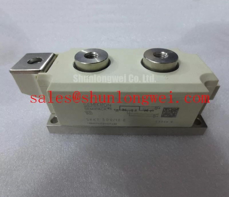
Begin the incoming inspection by isolating the rectifier, confirming the nameplate identity, and checking the power terminals and baseplate for loose hardware, heat discoloration, cracked insulation, or distorted mounting surfaces before applying a meter. The SKKT500/18E is a Semikron dual thyristor module in the SEMIPACK 5, Case A 60 housing, specified with VDRM and VRRM of 1800 V. Its official continuous current ratings are ITAV 500 A at Tcase 89 C and ITRMS 920 A, making the device relevant where a repair engineer must restore a high current controlled rectifier while retaining the original electrical and mechanical boundary conditions.
With the module removed from circuit influence where practical, compare measured terminal behavior against the known schematic and a known good phase leg where available. A cold resistance reading alone cannot prove dynamic semiconductor condition, particularly in an assembly containing multiple thyristor paths. It can, however, reveal an obvious low impedance power path, a damaged gate connection, or a wiring error before a controlled recommissioning attempt. Verify that the original circuit uses the same terminal arrangement, voltage class, cooling method, fuse coordination, and firing arrangement. The SKKT500/18E operating junction temperature range is officially specified as minus 40 C to plus 130 C.
SKKT500/18E Thermal Electrical Optimization: Mechanical Mounting Torque Sequence and Thermal Practical Tuning
Before fitting the module, inspect the heatsink contact area with a straightedge and clean both surfaces of hardened compound, metal particles, and residue. The copper baseplate must sit flat so heat leaves the semiconductor junction through the case and into the heatsink consistently across the full contact footprint. A localized gap can raise junction temperature even when the cabinet fan, current meter, and overall heatsink temperature appear acceptable.
Use the equipment manufacturer mounting sequence and the applicable fastener specification. Tighten opposing mounting points progressively to distribute pressure rather than drawing one side down first. Apply thermal interface material as a thin, continuous layer sufficient to fill surface irregularities, without allowing excess material to contaminate terminals or insulating areas. This is a Design Consideration, not an official SKKT500/18E torque or material thickness specification.
Field Alert: De energize, discharge, and verify the DC bus before loosening module terminals or mounting hardware, because stored energy and a shifted busbar can create immediate damage or injury risk.
At the specified sinusoidal operating condition, the module carries 500 A mean on state current at a case temperature of 89 C; the official table also lists 540 A at a case temperature of 85 C. These are defined conditions rather than a blanket cabinet current allowance. During commissioning, measure case temperature near the module mounting region and compare operating current, firing behavior, cooling airflow, and heatsink condition against the original equipment limits. A rising case temperature can reflect poor baseplate contact, reduced coolant or airflow performance, unequal current sharing between parallel paths, or abnormal commutation rather than a single cause.
For short duration fault coordination, the official surge rating is ITSM 15000 A for 10 ms at Tvj 130 C, with 17000 A for 10 ms at Tvj 25 C. The corresponding official I2t values are 1125000 A2s at Tvj 130 C and 1445000 A2s at Tvj 25 C. Fuse selection remains a system level Engineering Recommendation: compare the semiconductor fuse clearing behavior, prospective fault current, conductor contribution, and protection coordination against the actual rectifier documentation. The I2t figure is a fault withstand reference, not an instruction to operate the module at that energy level.
Transient Dynamics & Electrical Design: Commutation and Recovery Behavior on SKKT500/18E
In a phase controlled bridge, commutation moves current between device paths as line voltage and firing commands change. Thyristor turn-off and semiconductor recovery behavior affect current transfer, transient voltage stress, transformer interaction, and conducted disturbance. The supplied official ratings for this model establish voltage, current, surge, isolation, temperature, and package boundaries, but do not provide an official reverse recovery charge, peak reverse recovery current, recovery time, or softness value. Those values should not be inferred from the part number or substituted from a different module family.
When investigating ringing or repeated protective trips, capture the relevant line to line voltage, module current, gate firing reference, and DC output waveform using equipment rated for the measurement environment. Compare the timing to a healthy bridge section or the original control documentation. A waveform irregularity may indicate commutation stress, a firing synchronization issue, a loose bus connection, an unsuitable suppression network, or an upstream supply condition. The measurement must establish the mechanism before hardware changes are made.
Minimize the practical commutation loop area where the busbar layout permits, to reduce inductive overshoot during current transfer. Designers should then verify peak voltage margin against the DC link and incoming line conditions during switching tests. Suppression components are evaluated at the assembly level; a discrete module does not independently establish system EMC compliance. For a general reference on clamping surge transients, see Transient Voltage Suppression Diodes for Surge Protection.
The official isolation rating is Visol 3000 V r.m.s. at 50 Hz for one minute, with 3600 V for one second. This rating supports insulation coordination evaluation of the module itself under the stated test conditions. It does not replace an inspection of enclosure clearances, contaminated surfaces, busbar supports, cable routing, or the complete equipment insulation design. Keep terminals clean and ensure fitted covers, barriers, and original creepage features are restored before high voltage testing.
Field Diagnostics & Commissioning: Saturable Reactor and Snubber Sizing to Protect SKKT500/18E Topologies
For an installed rectifier that exhibits repeatable fuse operation or unstable current transfer, first document the fuse part number, phase sequence, busbar orientation, gate pulse routing, and suppression component connections. Look for overheated resistor bodies, swollen capacitors, cracked reactor insulation, and terminal joints that have lost clamping force. These inspections often identify an assembly issue without assigning a failure mechanism prematurely.
An RC snubber and a series saturable reactor are system components whose values depend on the transformer leakage characteristics, line impedance, current waveform, bridge layout, device firing strategy, and measured transient response. Their purpose can include moderating commutation voltage stress and limiting the rate of current rise under relevant conditions. Designers should establish values through the original circuit documentation and controlled oscilloscope tests, verifying both the electrical limits and component dissipation. No specific snubber capacitance, resistance, or reactor characteristic is an official parameter of the SKKT500/18E.
Use the official surge and I2t figures when reviewing the protection chain, while recognizing that upstream fault energy and fuse clearing behavior are system determined. Inspect each power terminal for proper seating and matching hardware. A connection with excess resistance can produce localized heating and uneven current distribution that is not visible in a simple no load test.
Where an alternative module is being evaluated during repair planning, compare its complete official data, case dimensions, terminal configuration, isolation rating, current ratings, and thermal interface requirements against the original design. The SKKT 106B08E can be reviewed as a separate Semikron module reference, but it requires an independent compatibility assessment and should not be treated as an automatic replacement for the SKKT500/18E.
Preventing Spurious Faults: Phase Controlled Rectification, Firing Angle Guidelines for SKKT500/18E
During phase controlled rectifier commissioning, confirm that every gate channel has the intended reference, synchronization, pulse presence, and phase relationship before raising load. The firing angle determines when the thyristor conducts within the AC cycle. As the command moves from a low delay toward a higher delay, the average DC output falls while input displacement and harmonic demands generally change. The exact transfer behavior depends on bridge topology, supply waveform, transformer arrangement, load inductance, control architecture, and conduction continuity.
A firing range spanning zero degrees through 150 degrees must therefore be evaluated from the equipment control specification and measured waveforms, rather than treated as a universal operating instruction. Missing or uneven firing pulses may produce reduced output, unbalanced phase current, transformer noise, or unexpected fuse stress, but each symptom requires verification at the control and power interfaces. Check gate drive connectors, synchronization inputs, control supply stability, and phase current traces before attributing a problem to the module.
For a high current green hydrogen electrolyzer DC power rectifier, engineers may evaluate this 1800 V, 500 A module against the original bridge position, thermal capacity, protection scheme, and control timing. The 920 A RMS current rating and the stated surge limits are useful official boundaries, yet the operating setpoint remains defined by the complete power supply. For broader context when reviewing high voltage switching margins and evolving power semiconductor approaches, consult Wide Bandgap Revolution alongside the original rectifier design documentation.