Content last revised on September 16, 2026
Assembly Integrity & Layout Architecture: Implementing Mechanical Mounting Torque Sequence and Thermal Path Control for SKKD260/08
With the module isolated from the circuit, first compare the diode-mode readings between each power terminal pair and the original circuit schematic before fitting SKKD260/08; an unexpected bidirectional low-resistance path can indicate an external parallel path or a failed power stage rather than a module-only condition.
The Semikron SKKD260/08 is a SEMIPACK 2 diode module rated at 800 V repetitive peak reverse voltage and 260 A average forward current at case temperature Tc = 93°C. Its 9100 A surge forward-current rating for 10 ms at 25°C provides a defined short-duration surge capability, while the stated 0.13 K/W junction-to-case thermal resistance is relevant when reviewing the heatsink path and sustained rectifier loading.
Inspect the SEMIPACK 2 baseplate, terminal surfaces, mounting points, and adjacent busbars before installation. The physical contact plane must be clean, flat, and free of hardened thermal compound residues. A thin, even thermal interface layer is a Design Consideration: its purpose is to fill microscopic surface irregularities without creating a thick thermal barrier between the module and heatsink.
The official Rth(j-c) of 0.13 K/W describes the thermal path from semiconductor junction to case, not the complete junction-to-ambient result. The final operating temperature therefore depends on the heatsink, airflow, interface material, mounting pressure, cabinet temperature, current waveform, and conduction duty. When replacing a failed rectifier in a medium-frequency induction melting or hardening furnace supply, technicians should retain the original mechanical stack-up unless the cooling assembly has been separately evaluated.
Fasten the module using a balanced sequence that brings the baseplate into even contact with the heatsink. Complete terminal tightening only after the module sits flat on the thermal surface, then check that busbars do not impose twist or bending force on the terminal area. The applicable mounting torque must be verified from the module documentation and the equipment’s hardware specification rather than assumed from a generic screw size.
🔧 Bench Diagnostic: Disconnect and discharge the DC link before removing power cables, then record cold diode-mode readings from the removed module as a comparison baseline for the replacement assembly.
The 260 A current rating is specified at Tc = 93°C, so a current rating alone is not a complete cooling approval. Design Consideration: inspect the original fuse coordination and semiconductor protection documentation for the equipment. The module’s 9100 A, 10 ms surge rating should not be treated as a substitute for correctly selected branch protection or for a fault-clearing study.
Benchtop Waveform Tuning: Reviewing Commutation Stress and RC Damping Around SKKD260/08
SKKD260/08 is a diode module, so it has no gate-drive circuit and does not use gate-trigger tuning. In a rectifier or freewheeling position, the practical benchtop task is instead to observe commutation behavior across the installed assembly. Probe placement should be short and controlled, because long probe ground leads can display ringing that belongs to the measurement loop rather than the power circuit.
RC damping and series reactor choices are system-level Design Considerations, not factory settings for this module. Their function is to control voltage overshoot and current-transition stress caused by transformer leakage inductance, busbar geometry, load characteristics, and commutating devices. Engineers should verify measured peak reverse voltage against the module’s official 800 V VRRM rating during representative switching and load conditions.
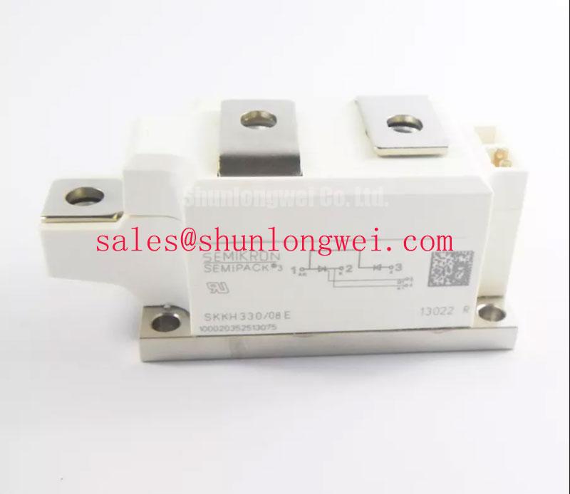
For furnace power supplies, an upstream or auxiliary rectifier stage may use a different current class. The SKKH330/08E can be reviewed as a separate circuit-level reference where the original topology calls for that device family and its terminal arrangement, voltage class, thermal path, and protection network have been checked. It is not an automatic substitute for SKKD260/08.
Semikron’s SEMIPACK thyristor and diode module information provides useful product-family context when confirming the intended module arrangement and mechanical platform. The exact terminal function must still be matched to the original equipment diagram before energizing the cabinet.
Assembly Integrity & Layout Architecture: Verifying Diode Polarity and Temperature-Dependent Forward Conduction
Do not apply thyristor gate-current, holding-current, or multi-pulse firing requirements to SKKD260/08. Those parameters belong to controlled thyristor devices and are not defining characteristics of a diode rectifier module. The correct incoming inspection is polarity verification: use a meter’s diode function to identify the expected forward-conduction direction between the relevant terminals, then compare both paths for consistency under the same cold test condition.
Forward voltage behavior changes with test current and junction temperature, so a handheld meter reading is a polarity and gross-condition check rather than a full production-characterization measurement. If one path differs materially from the other, isolate the module from parallel circuit paths and repeat the check. A controlled current source and appropriate thermal test method may be required where the equipment fault record suggests uneven current sharing.
Design Consideration: parallel paths in a high-current rectifier assembly should be assessed for equal busbar length, contact resistance, cooling conditions, and commutation timing. Static similarity alone does not prove dynamic current sharing. During a repair assessment, confirm that mating cables, bus joints, fuses, and heatsink surfaces have not changed from the original configuration.
Where a circuit review identifies a different Semikron device designation, the SKKH273/18E should be treated as a separate compatibility evaluation. Compare the complete electrical function, reverse-voltage requirement, current duty, footprint, terminal assignment, and cooling requirement before considering it in a service bill of materials.
SKKD260/08 Operational Boundaries: Evaluating Reverse Recovery Stress and 800 V Reverse-Voltage Limits
The official reverse-voltage boundary for SKKD260/08 is 800 V VRRM. This rating should be checked against the actual rectified supply, expected transients, transformer operating condition, and measured commutation overshoot. It should not be interpreted as a complete system insulation, EMC, altitude, or reliability certification. Those outcomes depend on the full assembly and require equipment-level validation.
Diode reverse recovery can interact with transformer inductance, circuit stray inductance, snubber components, and the switching characteristics of commutating devices. Without a module-specific recovery waveform specification in the available official parameters, no numerical reverse-recovery current or recovery-time claim should be assigned to this part. Engineering Recommendation: capture voltage and current waveforms under controlled operating conditions, then evaluate whether the observed ringing or heating is associated with layout, damping, loading, or another circuit condition.
For higher-duty rectifier and conversion systems, the technical discussion in The Race for Efficiency can support a broader review of modular power-path layout, thermal interfaces, and measurement discipline. Semikron’s CAL diode technology information also offers manufacturer context on diode technology, while the SKKD260/08 installation decision must remain anchored to its verified 800 V, 260 A, surge, thermal, and package specifications.