



Content last revised on September 29, 2026
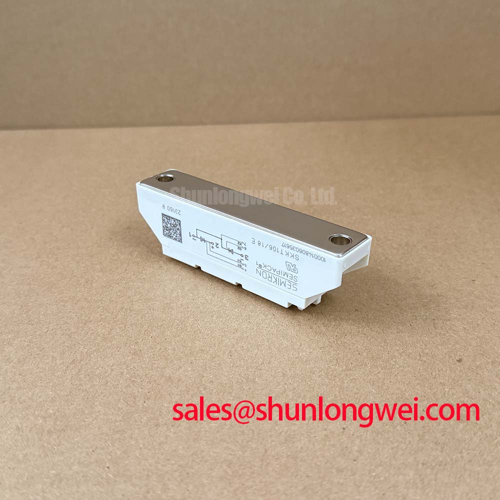
SKKT106/18E Assembly Integrity and Layout Architecture for Dynamic Firing Angle Adjustment
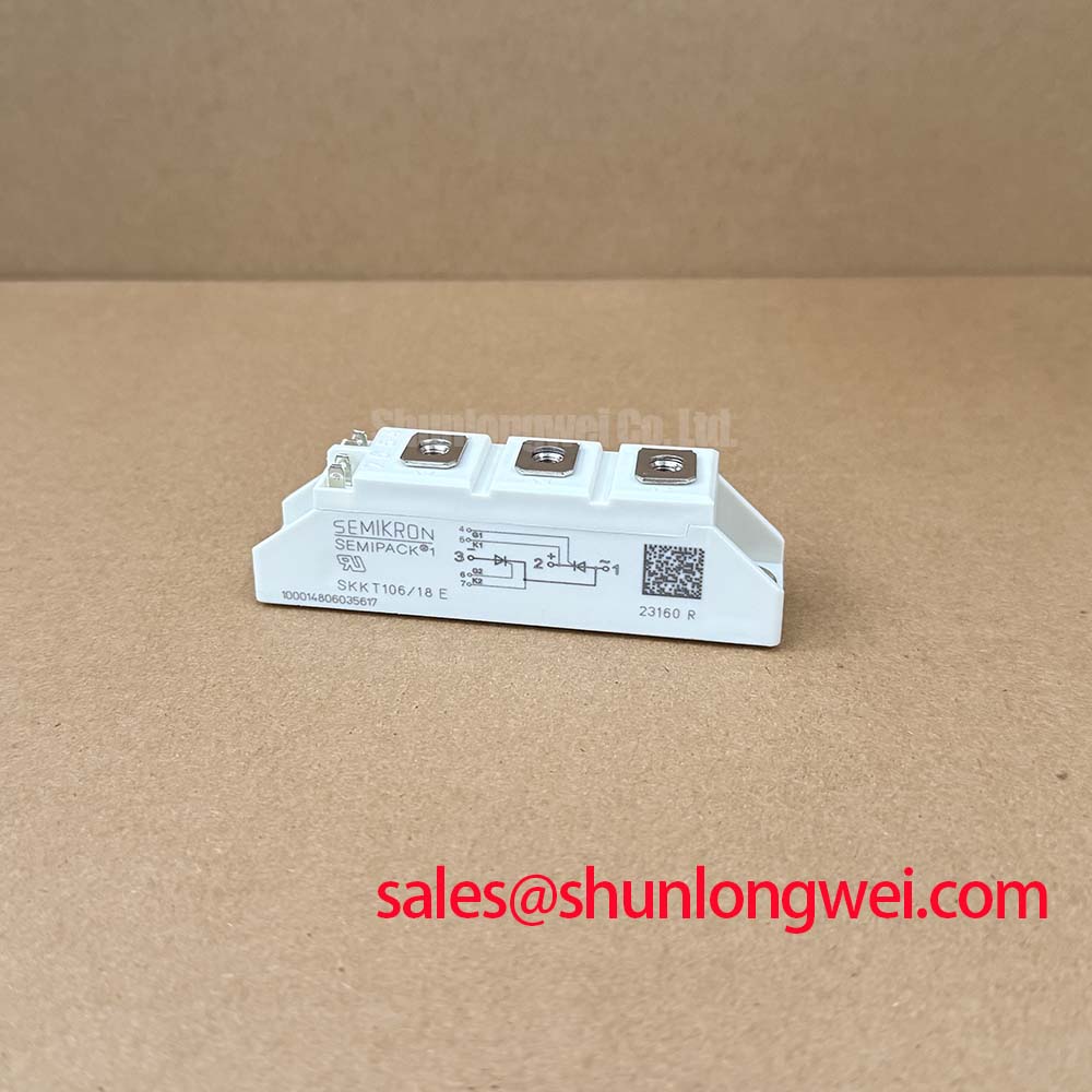
During assembly, confirm the original terminal arrangement and polarity before connecting the AC line, load, gate, and auxiliary control wiring. The available factory data identifies the electrical rating class and isolation capability, but it does not provide a universal terminal torque value, fuse coordination table, or complete mechanical drawing. Those details should be taken from the applicable Semikron documentation and the equipment manufacturer’s assembly instructions rather than inferred from the part number.
For a grid tied Static Var Compensator or thyristor switched capacitor bank, the firing angle determines when each controlled semiconductor enters conduction. As the firing angle is moved through the controller’s permitted operating range, the converter’s effective voltage, current waveform, displacement power factor, and reactive power exchange change with the connected network. The exact transfer characteristic depends on the bridge topology, phase sequence, control algorithm, transformer arrangement, and load impedance. Engineers should verify the command range, gate pulse timing, and commutation behavior using the actual SVC control hardware.
The 1800 V repetitive voltage rating is an electrical boundary, not a complete system surge design allowance. Minimize high di/dt loop area, maintain clear separation between power and gate wiring, and verify peak terminal voltage during switching tests. Gate drive isolation should also be checked for common mode transient behavior; the selected optocoupler or digital isolator must be evaluated against the switching environment and the control board’s layout.
For a neutral comparison during procurement, engineers may review the related SKKH273/18E alongside the SKKT106/18E, while confirming voltage, current, circuit configuration, dimensions, and thermal requirements from the relevant documentation.
Benchtop Waveform Tuning and Short Circuit Protection Coordination
Bench testing should begin with the power stage isolated from the live installation and with the gate circuit checked independently. The trigger requirement of VGT = 3 V maximum and IGT = 150 mA maximum at 25°C provides the official gate interface reference. It does not, by itself, define a suitable pulse width, pulse transformer design, series resistance, or controller output stage. Those values remain system dependent and should be validated at temperature and under the intended gate return layout.
Short circuit protection must be coordinated with the semiconductor manufacturer’s permitted surge and thermal limits. The published ITSM = 2250 A for 10 ms at 25°C describes a maximum non repetitive surge condition; it is not a permission to operate repeatedly at that current or a substitute for a semiconductor fuse coordination table. The selected fuse must be checked against the actual prospective fault current, clearing behavior, wiring impedance, and the module’s documented I2t withstand value. That value is not included in the supplied parameter set and should not be estimated from ITSM alone.
Use an oscilloscope with suitable differential and current probes to observe gate current, anode to cathode voltage, and fault clearing behavior. If the waveform shows unexpected ringing or delayed turn on, inspect gate loop inductance, isolation device timing, pulse transformer reset behavior, and control reference integrity before assigning the fault to the module. A controlled low energy test can help separate gate drive problems from power circuit problems.
Maintenance Note: Isolate the equipment before touching the module, and periodically inspect heatsink airflow, thermal interface condition, and terminal tightness according to the equipment service procedure.
Thermal Electrical Optimization and Reverse Recovery Evaluation
The supplied official data specifies the module’s thermal resistance as 0.35 K/W from junction to case per thyristor element. This figure supports thermal modeling, but the final case temperature depends on heatsink performance, interface condition, mounting pressure, airflow, ambient temperature, current waveform, and the number of conducting elements. Designers should verify the actual case temperature at the highest credible operating load rather than treating the rating as a guaranteed continuous field result.
The supplied parameter set does not specify reverse recovery charge, reverse recovery time, peak reverse recovery current, or soft recovery classification. Those values must be obtained from the applicable Semikron data sheet or test documentation before making a switching loss or EMI calculation. It would be technically unsafe to assign an Irrm or trr value to the SKKT106/18E without that source.
For commutation assessment, monitor the voltage and current transition at the module terminals under representative line impedance and gate timing. Minimize parasitic inductance in the commutation path to reduce overshoot, then verify the measured peak voltage against the 1800 V repetitive off state voltage boundary and the actual transient protection strategy. Snubber selection, AC line impedance, transformer leakage, and control timing should be tuned as a complete network.
Thermal compound, heatsink flatness, and clamping alignment deserve the same attention as electrical ratings. A distorted mounting surface or uneven pressure can increase the practical thermal path even when the nominal heatsink appears adequate. The module’s isolation voltage of 3600 V AC should also be considered alongside the complete creepage, clearance, insulation, and test arrangement of the assembled equipment. The Semikron SEMIPACK® thyristor and diode module information provides useful product family context for this evaluation.
AC Input Transient Overvoltage Clamping and Practical Tuning
AC input protection should be designed around the installation’s prospective surge environment, upstream transformer characteristics, cable length, and earthing arrangement. An MOV or RC network selected for a generic voltage class cannot be assumed suitable for every SVC or thyristor switched capacitor installation. The system integrator should verify continuous RMS voltage, temporary overvoltage exposure, surge current, energy handling, coordination with upstream fuses, and the required clamping level.
The SKKT106/18E provides an official repetitive blocking voltage rating of 1800 V and an isolation voltage of 3600 V AC. These specifications help define the semiconductor interface, but they do not constitute an IEEE 61000 4 5 system compliance claim. Surge immunity and EMC performance belong to the completed assembly, including the enclosure, wiring, protective earth, snubber placement, and control interface.
Place transient suppression with a short, controlled connection to the relevant power loop, while keeping high energy surge paths away from gate and feedback wiring. The RC snubber should be evaluated for voltage stress, pulse energy, resistor heating, and interaction with the AC network. MOV selection should account for repeated operating events as well as the single surge case. Verification requires captured waveforms at the module terminals, not only calculations from the nominal supply voltage.
In a larger converter cabinet, a related device such as SKKH330/08E may appear in an associated rectifier or complementary power stage. Compatibility must be established from circuit role, voltage class, current profile, mechanical arrangement, and thermal design. For broader industrial drive technology context, engineers can consult Unlocking Efficiency in Industrial Drives, while keeping its technology scope separate from this dual-thyristor module.