



Content last revised on October 1, 2026
SKKT250-18E Circuit Protection and Reliability: Fuse Coordination
| Parameter | Factory Specification |
|---|---|
| Model | SKKT250-18E |
| Manufacturer | Semikron |
| Product category | Thyristor module |
| Rated voltage | 1800 V |
| Rated current | 250 A under specified datasheet conditions |
| Package | Semipack |
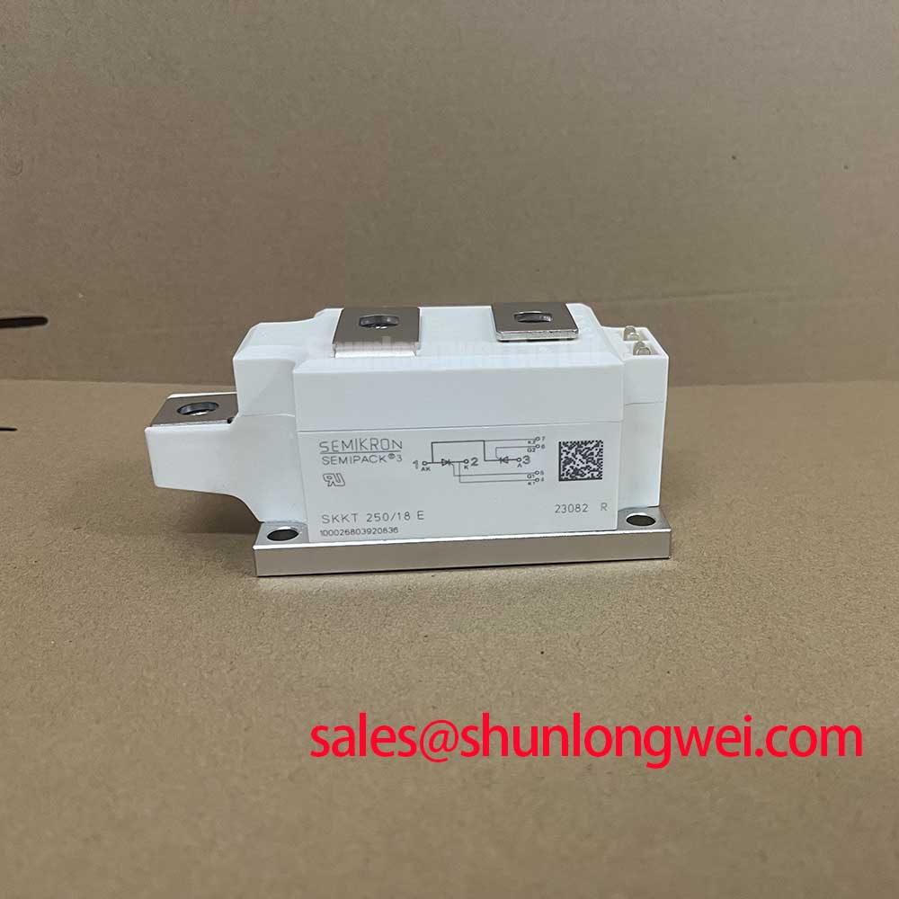
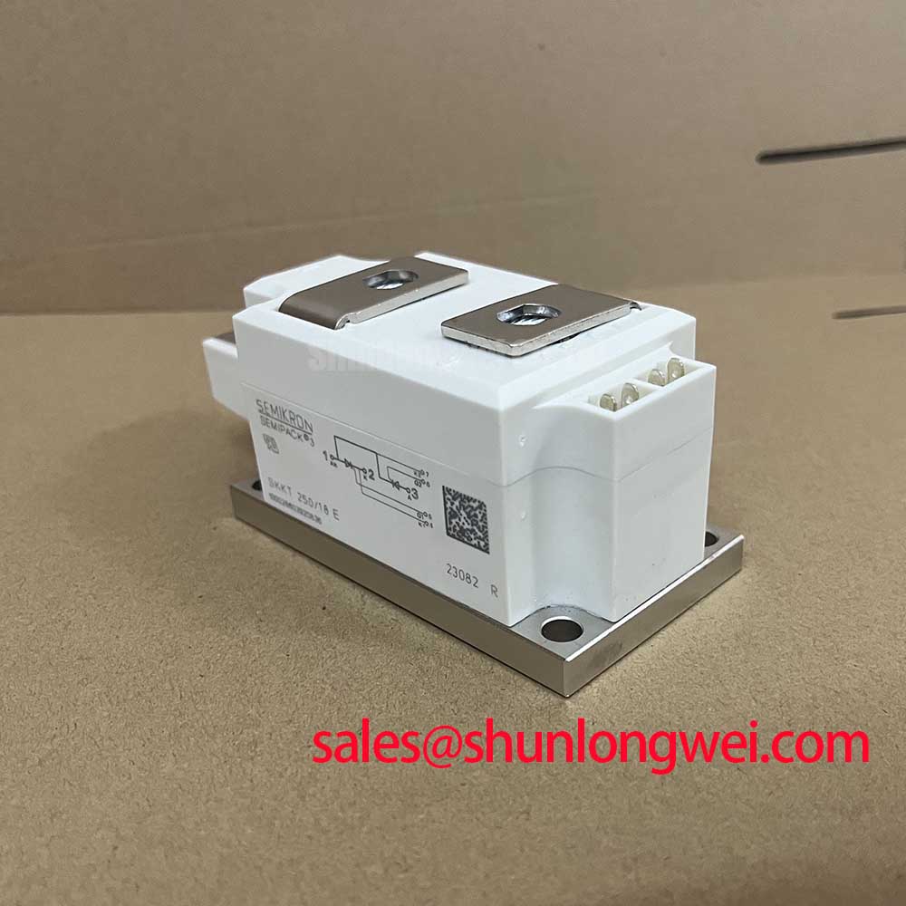
Isolate the power stage, discharge the DC link, and check the main terminals for heat discoloration, looseness, or mechanical movement before assessing a failed SKKT250-18E. The device is a Semikron Semipack thyristor module with a rated voltage of 1800 V and a rated current of 250 A under specified datasheet conditions. These ratings identify the component class and electrical boundary, but they do not by themselves establish a suitable fuse-clearing combination for a particular SVC or thyristor-switched capacitor assembly.
For a dead-short investigation, record the installed semiconductor fuse type, its published total-clearing I2t, prospective fault current, and the circuit inductance shown by the equipment documentation. Compare those values with the original Semikron coordination data for the exact module configuration. The supplied factory parameter set does not include a fuse I2t withstand value, so a protection decision should remain tied to the applicable device datasheet and fuse manufacturer coordination table. A fuse that interrupts the fault may still leave destructive electrical stress if wiring inductance, commutation conditions, or peak current differ from the evaluated installation.
Inspect every power connection as a complete interface: terminal surface, busbar flatness, washer arrangement, conductor support, and heatsink seating. Use the fastener torque specified for the actual Semipack hardware and equipment assembly. Field alert: do not reuse a distorted busbar or tighten a power terminal by feel, because uneven contact can create local heating that a current rating alone cannot reveal.
For upstream topology review, engineers evaluating the auxiliary or rectifier section may compare the related SKKD260/08 listing as a separate device reference. It should not be treated as an automatic substitute for the SKKT250-18E without checking circuit function, voltage class, current path, mounting geometry, and control requirements.
SKKT250-18E Thermal Interface: Junction to Heatsink Verification
Measure the cold-state mechanical condition of the module and heatsink, then inspect the contact footprint for rocking, tilt, contamination, or uneven thermal compound. The SKKT250-18E uses a Semipack package, while the supplied product data does not specify thermal resistance, baseplate dimensions, mounting torque, or permitted heatsink pressure. Those values must come from the applicable Semikron mechanical and thermal documentation rather than being inferred from the 250 A rating.
A thermal inspection should compare the failed unit with a known-good mounting position. Check whether the heatsink surface is clean and planar, whether the module sits without distortion, and whether the thermal interface compound covers the intended contact area as a uniform thin film. Excess compound can impede contact; insufficient or displaced compound can leave dry regions. The final assembly method is system-dependent and should be validated through temperature measurement at the intended load and switching condition.
For semiconductor construction and application context, consult Semikron's SEMIPACK thyristor and diode module information. Thermal results should be assessed with the actual airflow, heatsink orientation, busbar arrangement, and enclosure conditions. A replacement module with matching headline ratings can still require a separate mechanical and thermal qualification.
Field Diagnostics and Commissioning: Post-Surge Reverse Voltage Blocking
With the assembly isolated, test the external power path for unintended continuity, inspect gate and auxiliary wiring, and compare the module's terminal behavior with the known-good phase path. A post-surge fault may involve the semiconductor, fuse, commutation network, wiring, or control timing; a single cold resistance reading cannot identify the failed element with certainty.
Surge review requires the original device data for forward surge current, reverse blocking behavior, pulse duration, junction temperature, and recovery conditions. The supplied factory specifications confirm 1800 V rated voltage and 250 A rated current under specified datasheet conditions, but do not state an ITSM value or a 10 ms surge limit. Do not convert the rated current into a surge capability. Confirm the actual sinusoidal half-cycle event from the protection record or oscilloscope capture, then check whether reverse voltage was reapplied while the device was still thermally or electrically stressed.
Commissioning should include phase-to-phase comparison, gate circuit continuity checks, fuse status verification, and waveform observation during controlled energization. Minimize gate-loop parasitic inductance and verify that the firing circuit does not receive false pulses from commutation transients. For a broader power-conversion reference, engineers can review Peak Efficiency in Solar and Energy Storage when assessing multilevel switching arrangements.
Benchtop Waveform Tuning: RC Snubber and Commutation Stress
Capture the voltage across the module and the gate-to-cathode waveform at the device terminals while checking for overshoot, ringing, false triggering, and abnormal commutation timing. An RC snubber, damping resistor, or series reactor cannot be selected responsibly from the 1800 V rating alone because the required values depend on circuit capacitance, stray inductance, load current, firing angle, source impedance, and the measured transient.
Use the original application schematic to identify whether the network is suppressing excessive dv/dt, limiting commutation overshoot, or damping a control-loop resonance. Select the snubber as an engineering calculation from measured waveform energy and component voltage, pulse-current, and thermal ratings. The system designer should then verify the result on the bench across the expected operating range, including the highest practical current and the fastest switching transition. The same principle applies to series saturable reactors: their effect must be validated against the actual current waveform rather than assumed from a nominal module rating.
Gate wiring should remain short and physically separated from high-current commutation conductors where the equipment layout permits. In multi-device assemblies, designers should verify static and dynamic current sharing, gate-loop damping, and firing dead-time behavior through comparative waveform measurements. The Semikron bare-die product information provides additional manufacturer-level context for semiconductor technology, but it does not replace the exact SKKT250-18E application and mechanical documentation.