Content last revised on September 20, 2026
Assembly Integrity & Layout Architecture: Verifying Diode Module Conduction Paths for SKKD 46/18
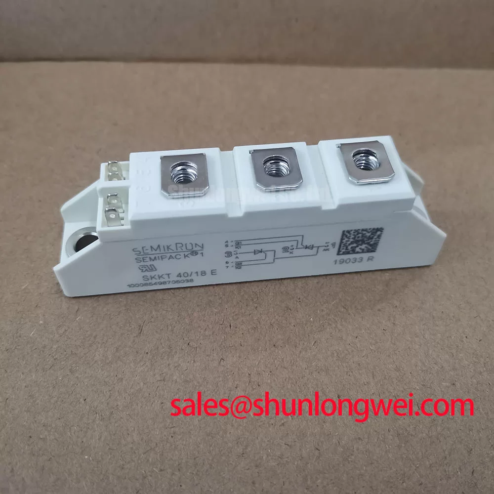
Begin incoming inspection by isolating the module from the power circuit, confirming the terminal markings against the equipment drawing, and comparing cold diode mode readings between the installed position and a known functional phase where available. The SKKD 46/18 is a Semikron diode module in the Semipack housing. Its stated electrical identity is 1800 V rated voltage and 46 A rated current. These figures should be checked against the original controller bill of materials, line voltage conditions, protection coordination, and heatsink assembly before a repair decision is made.
| Manufacturer | Semikron |
| Product model | SKKD 46/18 |
| Device category | Diode Module |
| Rated voltage | 1800 V |
| Rated current | 46 A |
| Housing | Semipack |
For a diode module installation, terminal identity is the first control point. A multimeter diode test can help establish whether the diode path is consistent with the circuit schematic and whether a gross short circuit is present. It cannot prove blocking performance at rated voltage, dynamic commutation behaviour, or load capability. Keep the module disconnected from energized power terminals during static checks, and record readings in the same polarity for each comparable module location.
The supplied product data identifies the 1800 V, 46 A and Semipack characteristics, but it does not provide a confirmed surge current, fuse clearing integral, terminal torque, insulation rating, or transient thermal impedance value. Those parameters must be taken from the applicable Semikron production datasheet and from the original equipment documentation rather than inferred from the housing or part family.
Conduction quality remains an important Design Consideration in rectifier assemblies. Unequal forward paths, a weak or damaged connection, unsuitable isolation, or unequal thermal conditions between phases can alter the current distribution and commutation behaviour. The power circuit should therefore be examined at the module terminals with an appropriately isolated measurement method while the system is operated only under controlled commissioning conditions. Designers should verify that the actual voltage, current, repetition method, and timing of the applied waveform meet the requirements stated for the installed device variant.
Busbar geometry also deserves inspection. Keep sensitive measurement and control wiring clearly separated from high current power paths where the system layout permits, because changing magnetic fields around power conductors can disturb measurement references and auxiliary circuits. This is a Design Consideration, not an official construction claim for SKKD 46/18. Inspect terminal faces for oxidation, heat discoloration, loose hardware, damaged insulating covers, and uneven conductor contact before reassembly.
💡 Bench Tip: Record cold diode mode readings before energizing a repaired assembly, because a repeatable baseline is more useful than relying on a single unreferenced meter result after a fault event.
Where an alternative module is being assessed during repair planning, SKKH273/18E can be reviewed as a separate product comparison, but terminal arrangement, circuit function, voltage rating, current rating, gate characteristics where applicable, thermal interface, and protection coordination must all be verified by the system engineer before any substitution. A matching housing appearance alone is not adequate evidence of electrical interchangeability.
Field Diagnostics & Commissioning: Evaluating Phase Conduction in SKKD 46/18 Topologies
In a controlled rectifier or motor soft starter topology, inspect the incoming three-phase waveform, the controlled-device trigger references where applicable, and the output phase balance before changing any firing-delay setting. The SKKD 46/18 is a diode module and does not provide gate-controlled firing. In assemblies that also contain thyristors, the firing angle determines how much of each AC waveform is applied to the load through those controlled devices. Moving the trigger point later in the half cycle reduces transferred average energy, while earlier triggering increases the conduction interval. The practical result depends on the complete topology, line impedance, motor condition, bypass arrangement, current transformer scaling, and controller logic.
For a high-voltage three-phase motor solid-state soft starter, the SKKD 46/18 should be evaluated as one element in a coordinated power path rather than as an isolated current switch. During commissioning, compare conduction and current waveforms across phases and observe whether phase current rises consistently as the controller changes its commanded ramp. A current imbalance can be associated with trigger synchronization in the controlled devices, line supply variation, connection resistance, load asymmetry, sensing error, or a device fault. It should not be assigned to one cause without waveform evidence.
Power factor and reactive power demand are system effects that change as the firing angle changes in controlled sections of the circuit. At delayed firing positions, the source current waveform can become less aligned with the supply voltage and less sinusoidal. The installation engineer should verify demand against the site supply constraints, controller settings, motor starting requirements, and applicable equipment documentation. The 1800 V rated voltage must remain an official electrical boundary within that assessment; it does not establish acceptable system overvoltage, line transient, or commutation margin by itself.
Check the driver outputs with the same channel reference and timing basis where the assembly includes gate-controlled devices. If a firing pulse is absent, irregular, or displaced relative to the expected phase reference, trace the control path through its isolation device, gate wiring, return conductor, connector, and controller output. Avoid probing live high-energy assemblies with non-isolated instruments or an uncertain ground reference. When integrating or repairing, engineers should verify peak voltage conditions under switching and line disturbance tests against the installed module rating and the original equipment protection scheme.
In systems that use additional rectification or auxiliary power sections, the SKKH330/08E is a relevant device to review separately within the wider power topology. Its presence in a related circuit does not establish that it performs the same function as SKKD 46/18 or that either module can replace the other.
Benchtop Waveform Tuning: Mitigating Stress via Semiconductor Protection Fuse Selection for SKKD 46/18
Protection fuse selection must begin with the approved module data and the original equipment fuse coordination information. A semiconductor fuse is selected to limit fault energy during a short circuit, but its suitability depends on its prearcing behaviour, total clearing behaviour, prospective fault current, supply source impedance, conductor inductance, and the relevant device withstand limits. The supplied product information does not state an SKKD 46/18 fuse I²t limit or a recommended fuse part number. It would therefore be inappropriate to publish a specific fuse rating or claim guaranteed fault containment for this module.
During a repair investigation, inspect the fuse body, fuseholder pressure contacts, busbar interfaces, and protective circuit connections. A visibly intact fuse does not demonstrate that it remains suitable for future protection duty. Verify its full identification and consult the equipment schematic, fuse manufacturer documentation, and approved device data. If a protective device has operated, inspect adjacent semiconductor modules and current-carrying joints because fault energy may have affected more than the component that opened the circuit.
Waveform measurements can show whether a commutation issue, controlled-device trigger problem, or external short circuit is creating abnormal stress. Use correctly rated differential voltage sensing and current sensing appropriate to the installation. Compare measurements with a known good signal path where possible. Excess ringing near a switching event may indicate a layout or measurement issue, and should be investigated by checking busbar paths, connection integrity, snubber components where fitted, and probe placement.
Minimizing parasitic loop inductance is a Design Consideration when the objective is reducing inductive voltage excursions during rapid current changes. The final arrangement is system determined and should be verified in controlled switching tests, including the actual DC link or line conditions, protective devices, wiring length, and load. Do not alter snubber values, fuse type, or control-network settings solely from a generic repair rule.
SKKD 46/18 Thermal Electrical Optimization: Evaluating Post-Surge Reverse-Voltage Blocking
After any overload or suspected surge event, allow the assembly to reach a safe deenergized condition before performing static checks. Inspect the module body, mounting plane, thermal compound condition, busbars, nearby fuses, and cable terminations. A cracked package, disturbed mounting hardware, heat marks, or damaged insulation barriers requires corrective assessment before power is restored. Static diode mode readings are useful for identifying gross anomalies, but normal readings do not certify reverse-voltage blocking at operating stress.
The SKKD 46/18 official voltage identity is 1800 V. Reapplication of reverse or blocking voltage after a surge should be assessed using the equipment’s original voltage protection design, operating waveform, ambient conditions, cooling condition, and the applicable production datasheet. The supplied data does not provide a confirmed sinusoidal half-cycle surge rating, post-surge recovery condition, repetitive peak blocking specification, or junction temperature limit. Those values must not be estimated from the nominal current rating or Semipack enclosure.
Thermal contact quality can influence the temperature reached by any power module under load. As a Design Consideration, use the equipment manufacturer’s specified mounting method, heatsink flatness requirements, thermal interface material process, and tightening sequence. Terminal hardware and base mounting hardware must be tightened only to approved values from the relevant mechanical documentation. Uncontrolled torque values can damage threads, distort interfaces, or produce unreliable electrical contact.
When abnormal blocking or commutation behaviour is suspected, capture the voltage waveform with the actual load and supply conditions represented. Confirm whether the event correlates with trigger timing in controlled devices, line transients, thermal state, a bypass contactor transition, or a protection response. For broader context on controlled power conversion behaviour and resonant switching concepts, see Resonant Topologies in Home Appliances. Semikron’s SEMIPACK® thyristor and diode module information and CAL diode technology information provide useful product family context, while the exact module documentation remains the controlling source for device-specific limits.