

Content last revised on September 15, 2026
SKKT132/14E Circuit Protection and Reliability During High Peak Current
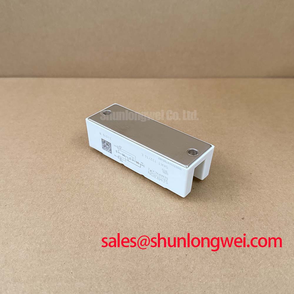
Begin incoming inspection with the module fully isolated: record the label, inspect the case and terminals, then compare the marked terminal arrangement with the Semikron documentation before applying any test voltage. A cold-state comparison between the replacement unit and a known-good module is useful, but resistance readings alone do not confirm thyristor blocking capability.
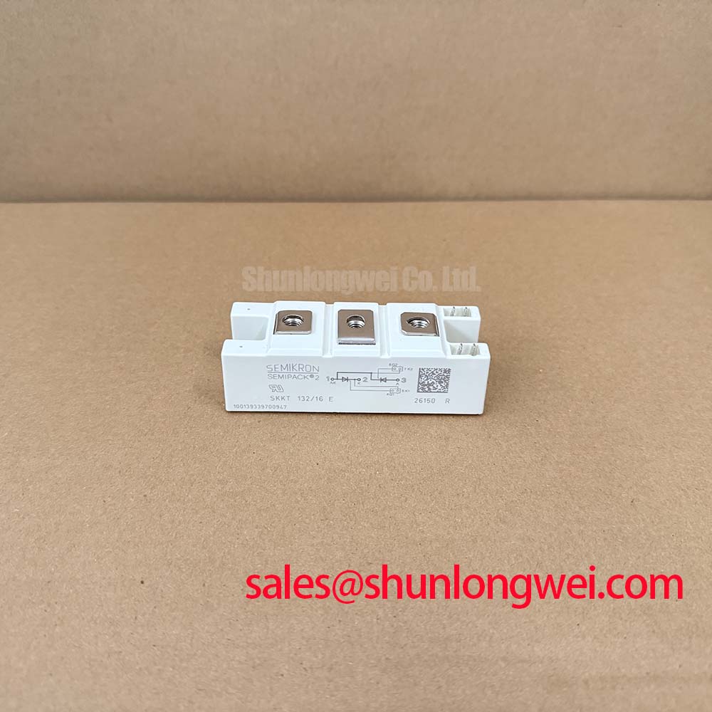
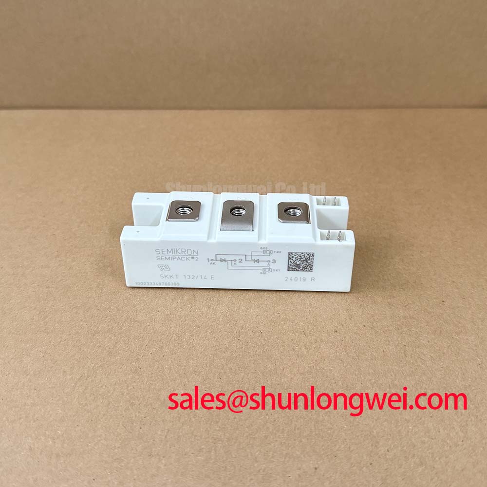
SKKT132/14E is a Semikron thyristor module classified for high-current power conversion and industrial motor-control assemblies. Its official repetitive peak reverse voltage and repetitive peak off-state voltage rating is VRRM / VDRM = 1400 V. The official average on-state current rating is IT(AV) = 130 A at Tc = 87°C, while the RMS on-state current rating is ITRMS = 220 A. These values describe the semiconductor rating under their stated conditions; the complete soft-starter assembly must still account for enclosure temperature, airflow, conduction angle, and current waveform.
| Parameter | Official Specification | Engineering relevance |
| VRRM / VDRM | 1400 V | Repetitive reverse and off-state voltage capability |
| IT(AV) | 130 A at Tc = 87°C | Average on-state current rating per thyristor |
| ITRMS | 220 A | RMS on-state current rating |
| ITSM | 4000 A, 10 ms at 25°C | Non-repetitive surge current capability |
| I²t | 80 kA²s at 125°C | Surge and fuse coordination reference |
| Rth(j-c) | 0.19 °C/W per thyristor | Junction-to-case thermal path |
| dv/dt | 1000 V/µs | Critical off-state voltage rise rate |
The ITSM = 4000 A for 10 ms at 25°C rating is a fault-survival reference, not a permissible repeating operating current. When checking a high-voltage three-phase motor solid-state soft starter, compare the prospective fault pulse and the selected semiconductor fuse against the module’s I²t = 80 kA²s at 125°C value. The fuse manufacturer’s clearing characteristics, pre-arcing I²t, coordination table, and actual prospective short-circuit current must be evaluated together.
At 50 Hz, the 10 ms condition corresponds approximately to a single half-cycle reference in an AC fault assessment. Before reverse voltage is reapplied, the protection study should verify that the switching event, fuse interruption, commutation behavior, and cooling conditions remain inside the documented device limits. Do not treat the 1400 V rating as a system insulation approval or as independent compliance with an equipment safety standard.
The module’s dv/dt = 1000 V/µs official rating is relevant when line transients or commutation spikes appear across an off-state thyristor. Snubber selection, line impedance, transformer leakage, and wiring inductance remain system-level variables. Designers should verify the actual voltage waveform with an appropriately rated differential probe during controlled switching tests.
Assembly Integrity and Thermal Interface Across the Baseplate
The official Rth(j-c) = 0.19 °C/W per thyristor only describes the junction-to-case thermal path. It does not include the interface resistance between the module baseplate and heatsink, nor the heatsink-to-ambient path. For this reason, a replacement inspection should include the mating surface, mounting hardware, thermal interface material, and cooling assembly rather than focusing on the module body alone.
Clean both mating surfaces according to the equipment manufacturer’s service procedure and check for burrs, high spots, contamination, or distortion. Thermal compound should be spread as a thin, even film that fills surface irregularities without creating a thick insulating layer. The correct application amount is determined by the surface finish and interface material instructions; it should not be inferred from the module’s current rating.
Flat, even contact pressure is important for a pressure-mounted or bolted power module. Tighten the fasteners progressively and diagonally where the mechanical arrangement requires it, using the original hardware and the manufacturer’s specified torque. A generic mounting torque value must not be presented as an official SKKT132/14E specification because the correct value depends on screw size, washer arrangement, heatsink construction, and module mounting instructions.
⚡ Safety Interlock Note: Disconnect the DC and AC sources, confirm the discharge state of the power circuit, and never insert or remove control wiring while the soft starter is energized.
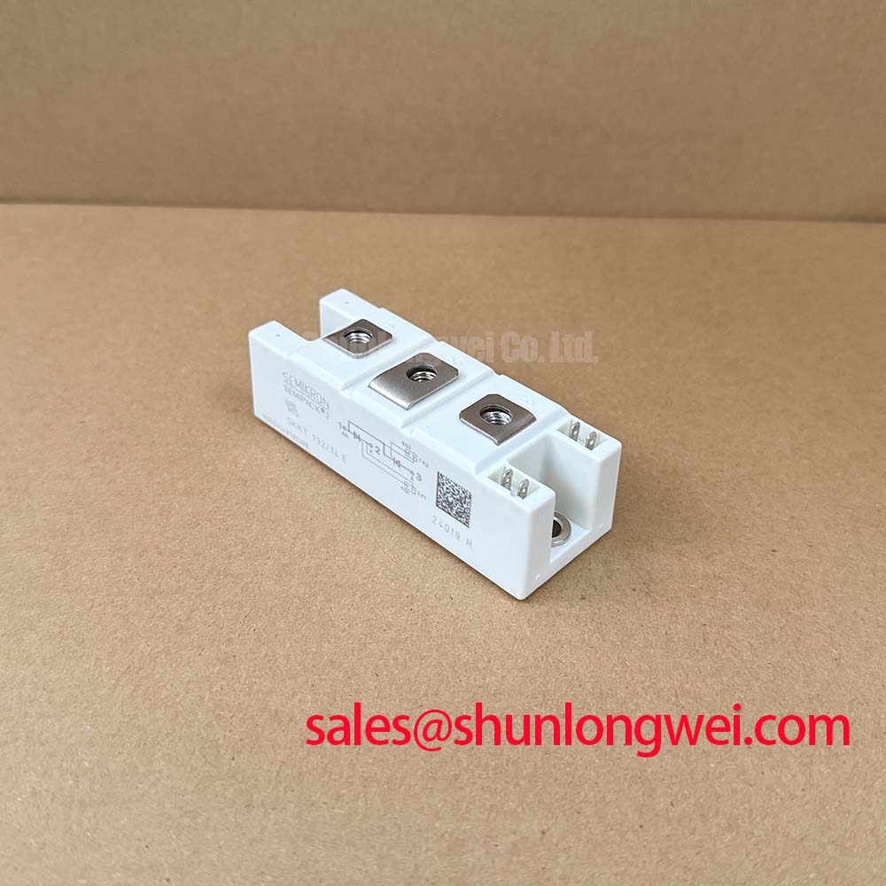
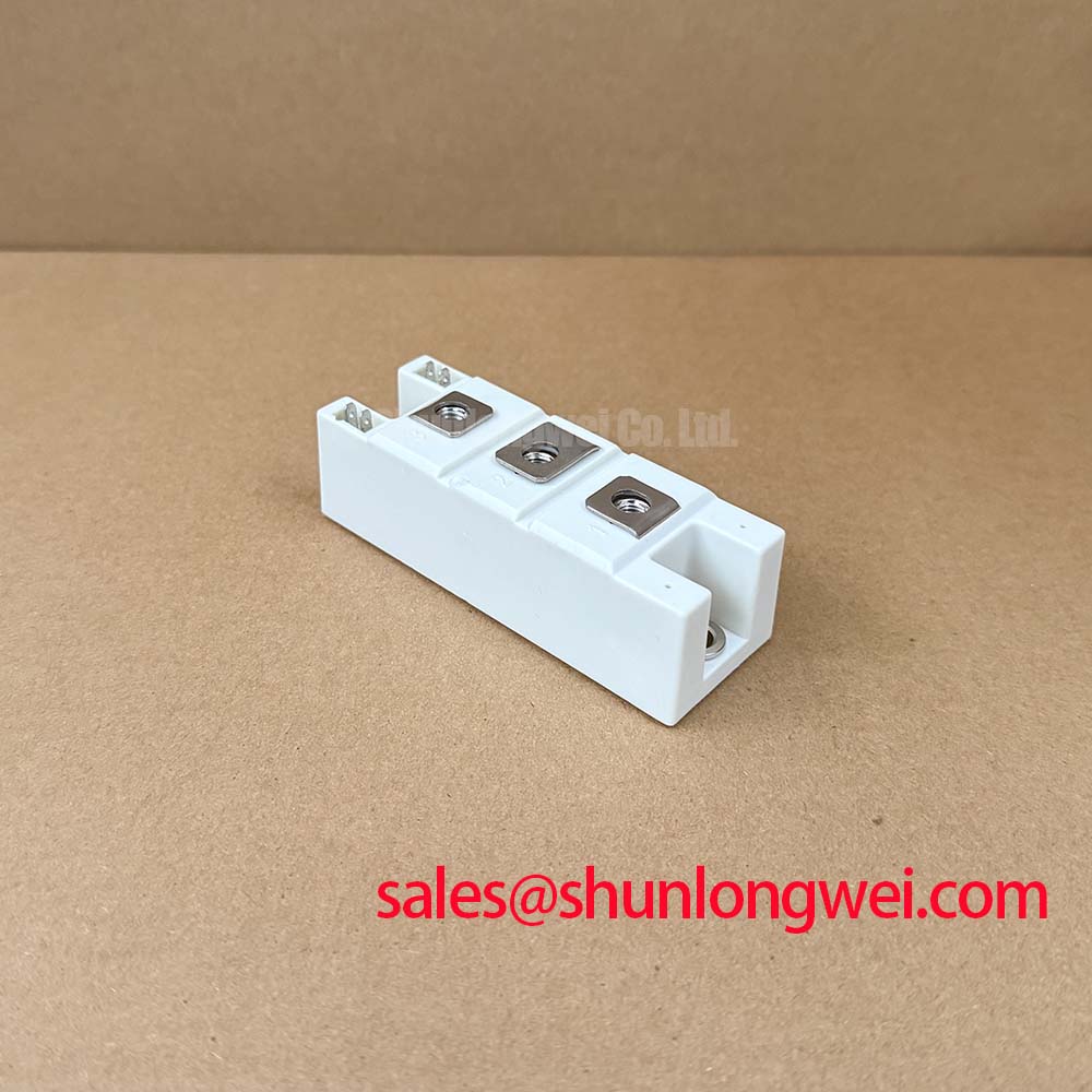
After mounting, inspect the terminal connections for damaged threads, loose lugs, and signs of previous overheating. The power terminals must follow the original phase and thyristor path markings; do not assume that a visually similar terminal position has the same electrical function. Control terminals should be checked against the module drawing and the soft-starter controller schematic before a gate pulse is applied.
For repair teams comparing current capacity, the neutral reference SKKT 250/14E can help structure a technical comparison. It should not be treated as an automatic substitute: mechanical dimensions, terminal layout, gate characteristics, thermal conditions, fuse coordination, and controller compatibility require separate verification.
Pulse-Transformer Isolated Firing Circuit and Practical Gate Checks
A pulse-transformer isolated firing circuit should be checked from the controller output toward the module gate and cathode terminals. Confirm polarity from the original wiring documentation, inspect the transformer secondary connections, and compare the cold-state continuity of each channel with the corresponding channel in a known-good assembly. A continuity result cannot establish the required IGT, VGT, gate pulse width, or gate current because those values are device and circuit dependent and are not included in the supplied parameter set.
During live commissioning, designers should verify the gate waveform at the module terminals rather than only at the pulse-transformer primary. Cable impedance, transformer leakage, connector condition, grounding arrangement, and probe loading can alter the pulse delivered to the gate. Where the controller supports repeated firing pulses, the pulse train should be evaluated against the thyristor firing requirements stated in the applicable Semikron documentation.
The proposed engineering focus on a gate-current rise condition such as diG/dt greater than 1 A/µs must not be assigned to this exact model without a confirmed manufacturer source. Treat it as a design-review question: verify that the firing circuit provides a clean, sufficiently strong pulse under the actual temperature, wiring, and transformer conditions. The same caution applies to back-porch current, pulse duration, and multi-pulse timing.
In a three-phase soft starter, phase timing and controller interlocks should prevent unintended simultaneous commands during commissioning. The required dead time is system-determined and should be validated with isolated measurements of all phase firing signals. Oscilloscope checks should compare gate-to-cathode behavior with the corresponding anode-to-cathode voltage so that a missing pulse is not confused with a commutation or load-side condition.
Semikron’s general product information for Semikron SEMIPACK® Thyristor / Diode Modules provides useful background for interpreting module applications. The exact terminal identification and firing limits for a service replacement should come from the applicable product documentation and the original equipment schematic.
Snubber and Saturable-Reactor Evaluation for dv/dt and di/dt Control
When an off-state thyristor experiences a fast voltage transition, the official dv/dt rating of 1000 V/µs provides the comparison point. The actual circuit may produce a different transient because of cable length, transformer leakage, commutation overlap, contactor behavior, and stray inductance. An RC snubber should therefore be assessed from measured anode-to-cathode waveforms, capacitor pulse capability, resistor pulse energy, and the switching frequency of the complete equipment.
Do not select Rs and Cs from the voltage rating alone. The snubber must control unwanted voltage rise without creating excessive reactive current, resistor heating, or capacitor stress during normal AC operation. Designers should verify the resulting peak voltage and current at the module terminals during start, stop, fault interruption, and line-reapplication tests.
A series saturable reactor can be considered where the equipment topology produces a severe current rise during firing or fault transfer. Its saturation behavior, volt-second capability, core temperature, insulation system, and interaction with the motor and transformer must be evaluated by the system designer. The SKKT132/14E official parameters provide current, surge, thermal, and voltage boundaries, but they do not define a universal reactor size or snubber network.
For broader selection work involving voltage class, current stress, cooling, protection coordination, and switching behavior, engineers can consult the Power Semiconductor Selection Guide alongside the original Semikron documentation. Final acceptance should be based on terminal inspection, controlled low-energy checks, insulation testing appropriate to the equipment, and waveform verification at the installed module.