

Content last revised on November 4, 2026
Transient Dynamics and Electrical Design for SEMIX353GB126V1
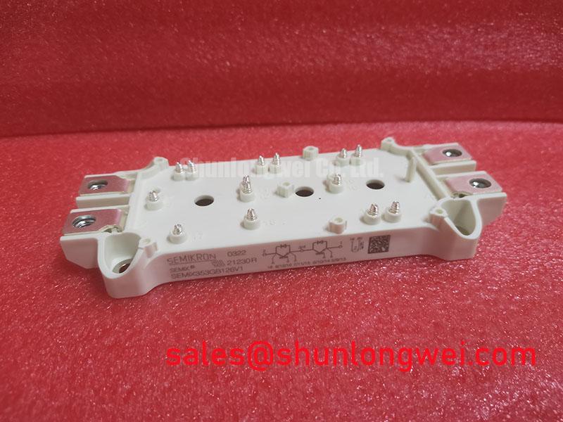
When investigating false gate triggering or irregular switching in an inverter welder or medium-frequency induction heating supply, start at the circuit connections: trace the gate-drive return to the exact emitter terminal shown in the module’s applicable pinout. Do not assume that a separate auxiliary Kelvin emitter is present on this part. The supplied product information does not specify its terminal configuration, so the schematic and the manufacturer’s module documentation must establish which terminals are provided and their intended use.
If the module documentation identifies a dedicated driver-return terminal, keep its gate-drive loop separate from the high-current commutation path as the circuit layout permits. Load-current changes through shared conductors create voltage differences that can disturb the gate-to-emitter signal. Inspect the driver return, power connections, and board routing together; a clean-looking gate waveform measured against the wrong reference point can conceal the disturbance seen by the device.
For a field check, compare the gate-to-emitter waveform at the module terminals with the driver output during the relevant switching event. Use an appropriately rated differential probe and a measurement setup suited to the circuit’s common-mode voltage. Look for unexpected excursions, ringing, or differences between the driver output and the voltage at the device. Correlate those observations with the switching sequence and current path before changing gate resistance or drive settings.
Design Consideration: Minimize unnecessary shared impedance between the gate-drive return and the power-current path, then verify the result under the actual operating conditions. Clearance and creepage requirements depend on the system voltage, pollution environment, insulation design, and applicable standards; they are not established by the module’s voltage rating alone.
Switching overshoot is affected by commutation-loop parasitics and current transitions. For a focused explanation of the underlying mechanism, see Stray Inductance, Transient Voltage Overshoot. Treat the discussion as a circuit-design reference, not as a device-specific switching limit. The Semikron-Danfoss power electronics and modules hub provides manufacturer product information; use the documentation for the exact module variant when confirming pin functions and operating limits.
SEMIX353GB126V1 Circuit Protection and Mechanical Reliability
Inspect the mounting and power-terminal assembly for signs of movement, uneven seating, damaged threads, or strain from rigid busbars before assessing electrical protection. Mechanical loads transferred through terminal connections can stress the assembly, particularly where vibration or repeated thermal cycling is present. Confirm the specified fastener, washer arrangement, thread engagement, and tightening procedure against the applicable manufacturer documentation; no model-specific torque or engagement depth is included in the supplied product parameters.
During replacement, support busbars and cables so their weight or alignment does not pull against the module terminals. Tighten connections using the documented procedure and suitable tools, then check that the assembled conductors remain seated without imposing visible mechanical force. A maintenance record of connection condition and any observed temperature change at the power joints can help identify developing contact or airflow issues without treating one symptom as proof of a single failure cause.
In the gate-drive circuit, complementary devices require interlocking and dead time appropriate to the switching devices, driver delays, and operating conditions. Shoot-through can result when both devices in a leg conduct at the same time; dead time that is excessive can also affect switching losses and output behavior. Set and validate these controls at the system level using the actual driver, topology, and switching sequence rather than assigning a generic value to this module.
Protection coordination also spans the power semiconductor, gate driver, current sensing, and upstream protective devices. A fuse’s clearing behavior and I²t characteristics must be assessed against the system fault conditions and the semiconductor’s documented limits; a fuse alone should not be assumed to interrupt every destructive short-circuit event in time. Where desaturation detection or controlled turn-off is used, assess detection delay, turn-off behavior, and resulting voltage excursions as a coordinated protection design. The supplied product data does not state short-circuit withstand time, SCSOA, or protection thresholds.
For maintenance planning, remove accumulated dust from the heatsink and airflow path, and inspect the thermal interface when the assembly is opened for scheduled service. Maintenance Note: Record changes in power-terminal temperature and verify that cooling airflow remains unobstructed after reassembly.
For parts evaluation, SKET400/12E is another listed device to assess against the application. Do not treat it as a drop-in replacement based on its listing alone: compare the manufacturer’s pinout, electrical ratings, package, thermal interface, and switching characteristics with the circuit and mechanical assembly.
Field Diagnostics and Commissioning for SEMIX353GB126V1
Check insulation only with the module isolated from the rest of the circuit and with the test method, voltage, and acceptance criteria specified for the complete equipment assembly. The supplied product parameters do not establish a terminal-to-baseplate insulation resistance limit, a test voltage, or a permissible creepage distance for SEMIX353GB126V1. Do not apply an assumed insulation-test threshold to the module or connected electronics.
Before an insulation test, disconnect or protect gate drivers, sensing circuits, snubbers, and other components that could be affected by the test instrument. Identify the test points from the equipment schematic and module documentation, then record the test conditions and result. If readings are unstable or differ from the equipment’s established baseline, inspect for contamination, moisture, damaged insulation, and unintended electrical paths before deciding whether the module or another part of the assembly is responsible.
Airborne dust and condensation can affect equipment insulation and cooling. Inspect enclosure seals, ventilation paths, and the module area for deposits or moisture, especially after storage or a change in ambient conditions. Clean using a process appropriate to the equipment and materials; avoid leaving conductive residue or moisture around power connections. Confirm that the assembly is dry and correctly reconnected before commissioning.
During initial operation, observe the equipment’s current, switching behavior, cooling performance, and protection indications within the machine’s approved commissioning procedure. For industrial inverter welders and medium-frequency induction heating supplies, compatibility depends on the complete converter topology, control settings, thermal design, and mechanical installation, not on voltage and current ratings in isolation. The manufacturer’s MiniSKiiP power modules page concerns a separate product line and should not be used as a substitute for SEMiX-specific documentation.