


Content last revised on September 20, 2026
Assembly Integrity and Layout Architecture for the CM2500DY-24S
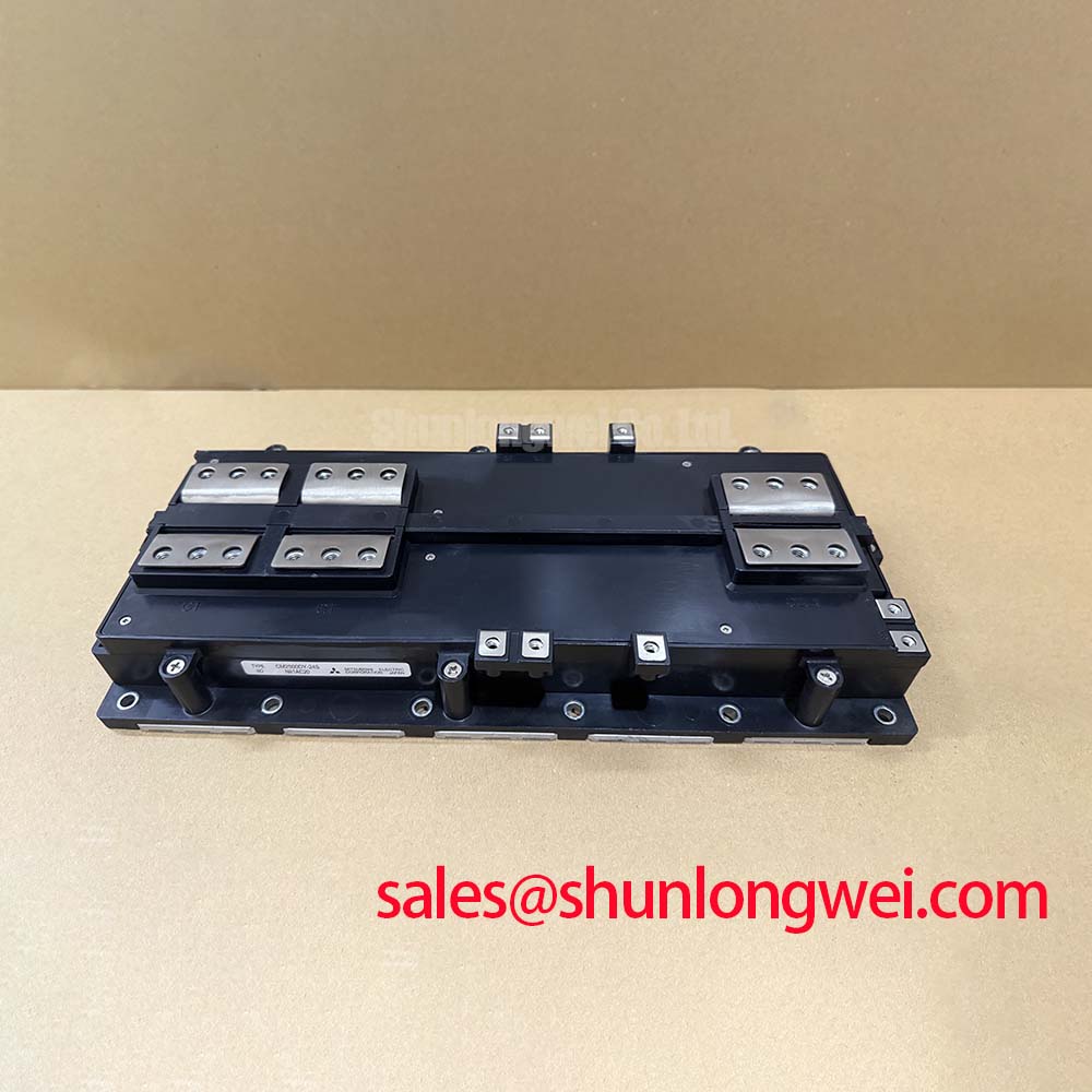
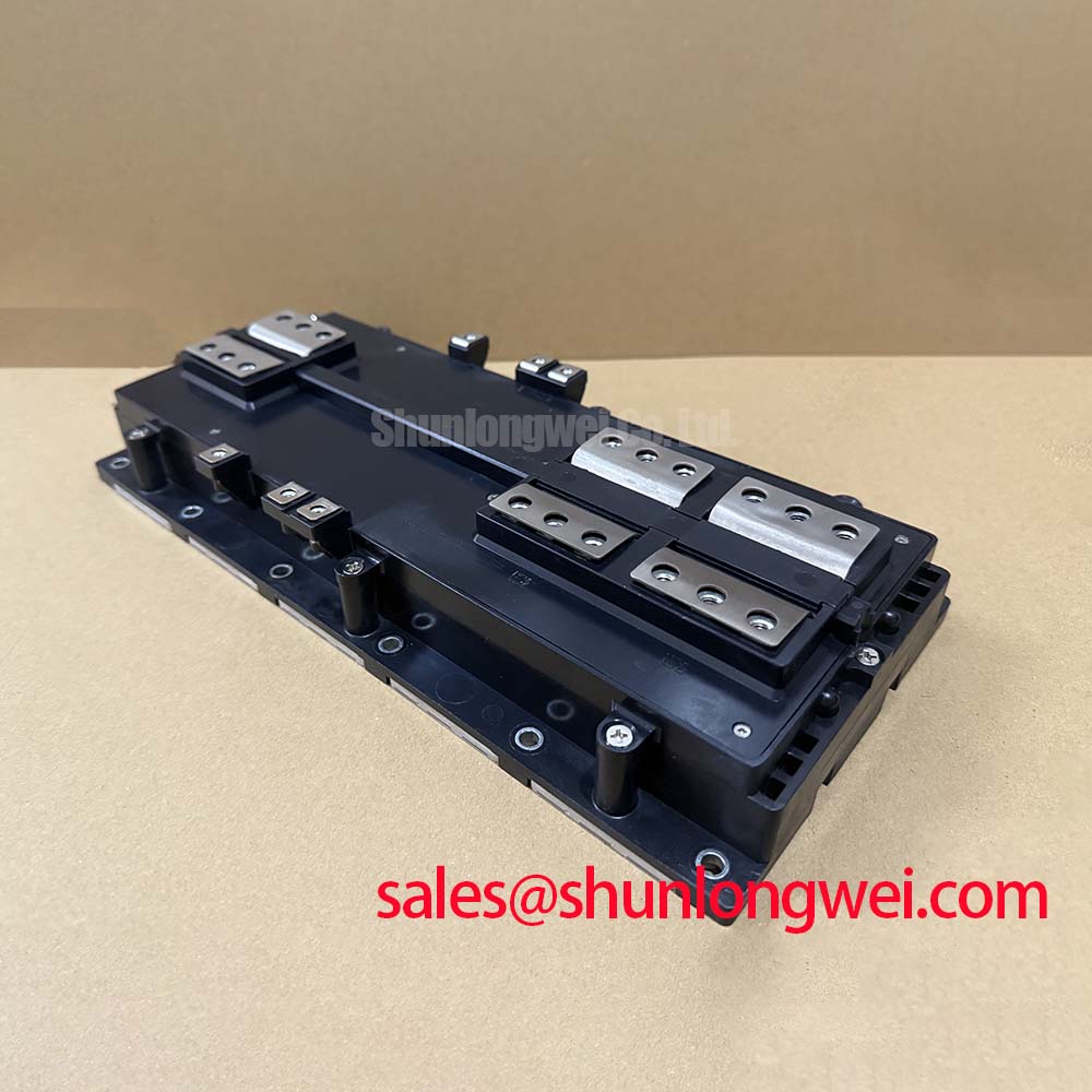
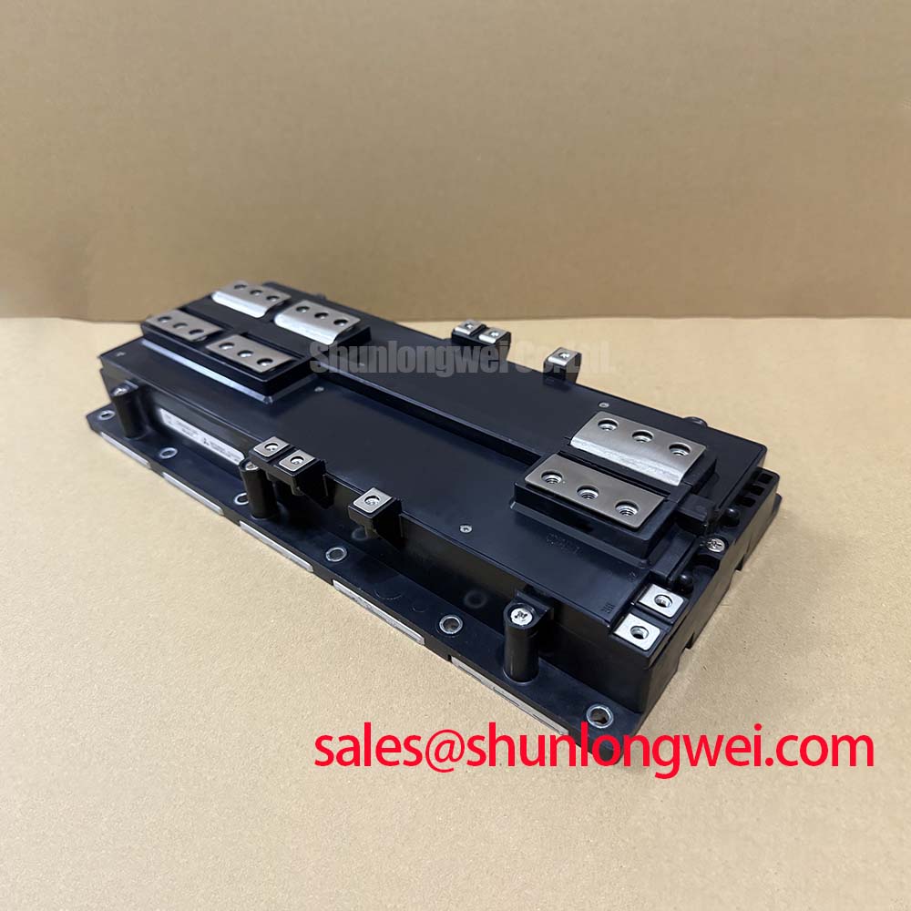
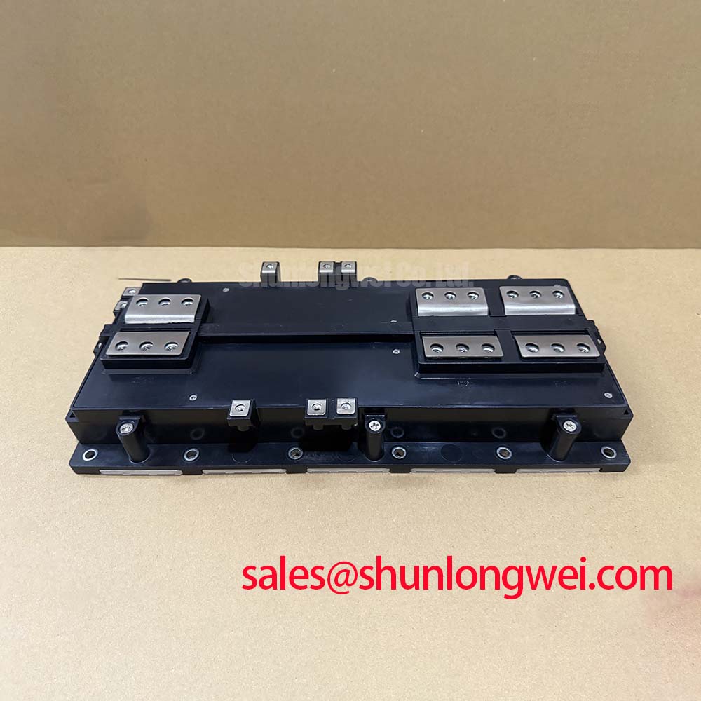
The Mitsubishi Electric CM2500DY-24S is a high-current IGBT module rated at 1200 V collector-emitter voltage and 2500 A continuous collector current at case temperature of 80°C. Its official typical collector-emitter saturation voltage is 1.80 V at 2500 A, with 2.40 V maximum at the same current condition. These ratings establish the device boundary, but actual converter performance still depends on busbar geometry, cooling contact quality, gate-drive behavior, and protection response.
For a utility-scale centralized battery energy storage PCS, the module can be evaluated within a bidirectional inverter bridge where large DC-link currents reverse between battery racks and the AC conversion stage. The layout objective is to keep the commutation path physically compact and symmetrical. During turn-off, parasitic inductance creates an overshoot that follows the relationship between DC-link voltage, loop inductance, and current-change rate. The system team should measure switching-node voltage at the module terminals and verify peak voltage against the 1200 V official rating under the actual DC bus, load current, temperature, and gate-drive conditions.
Planar laminated busbar arrangements are commonly considered because closely coupled forward and return conductors can reduce commutation-loop inductance. This is a Design Consideration, not a CM2500DY-24S factory specification. The module, local DC-link capacitors, snubber path, and busbar return route should be reviewed as one current loop rather than as separate mechanical parts. Unequal conductor lengths between parallel positions can produce unequal switching stress even when measured DC current appears balanced.
Snubber selection should be based on measured ringing frequency, peak overshoot, stored energy, capacitor ripple capability, and the converter’s actual switching sequence. A capacitor that improves one switching transition can alter ringing during the opposite current direction, which matters in bidirectional PCS operation. Engineers should validate the final arrangement with properly rated differential voltage probes and a known-good measurement method, avoiding long probe ground leads that can distort the waveform.
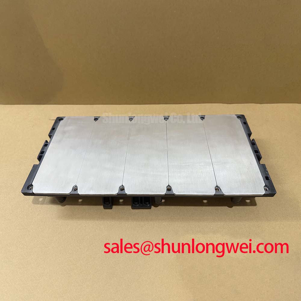
The physical interface should also be treated as a serviceable thermal joint. Remove old thermal-interface residue from the heatsink, check the mounting surface for flatness and debris, and use the installation procedure specified by the equipment manufacturer. Maintenance Note: Regularly monitor terminal and heatsink contact temperature rise while checking that cooling-air passages remain clear of dust accumulation.
Field Diagnostics and Commissioning of Galvanically Isolated Gate Drives
Before enabling a replacement power stage, verify the gate-drive board supply rails, isolation barrier condition, gate-command reference, desaturation sensing path, and complementary interlock logic with the DC link disabled. The CM2500DY-24S is a power module, not a complete protected switching assembly; gate isolation performance, common-mode transient immunity, and fault response are determined by the surrounding driver circuit and system architecture.
A Design Consideration for high-power bridge legs is galvanic separation between control electronics and the power stage. Reinforced isolation capability and common-mode transient behavior should be verified from the gate-driver manufacturer’s documentation and tested under the actual converter switching environment. A gate command that looks correct on a bench may behave differently when the switching node moves rapidly relative to the control ground.
Interlock, desaturation response, and controlled fault shutdown
Commissioning should confirm that the upper and lower switching commands cannot overlap under normal operation, startup, shutdown, controller reset, or auxiliary-supply interruption. Dead-time is system-determined: it must account for the installed driver propagation characteristics, actual device switching behavior, operating temperature, current direction, and measurement results. It should not be copied from another converter simply because the voltage class appears similar.
The official short-circuit withstand time for the CM2500DY-24S is 10 µs, specified at VCC = 600 V, VGE = 15 V, and junction temperature of 125°C. This is an official device specification under stated test conditions, not a guaranteed protection delay for every system fault. The desaturation circuit, controller logic, soft-turn-off behavior, stray inductance, and fault current rise all affect real equipment response. During commissioning, engineers should capture collector-emitter voltage and gate-emitter voltage together during controlled protection tests, then confirm that the shutdown waveform remains within the evaluated system voltage boundary.
If nuisance protection events occur, they may indicate noise coupling, an unsuitable blanking arrangement, an incorrect sensing reference, unstable auxiliary supply behavior, or a genuine overcurrent condition. Oscilloscope evidence should be compared with the known-good driver channel and the controller fault record before changing component values. For broader context on IGBT operating environments and converter applications, see Industrial Applications.
Mitsubishi Electric’s high-voltage HVIGBT module information provides useful manufacturer-level context for power-semiconductor families. Isolation, electromagnetic compatibility, and converter-level safety compliance must be assessed for the complete equipment rather than inferred from the module alone.
CM2500DY-24S Operational Boundaries in Bidirectional Power Conversion
In a centralized battery energy storage PCS, active power can flow from battery racks to the grid and return during charging. This reverses current paths through IGBT and freewheel-diode functions across the bridge, while repeated dispatch cycles can impose changing thermal conditions. The CM2500DY-24S provides an official IGBT junction-to-case thermal resistance of 0.011°C/W and diode junction-to-case thermal resistance of 0.022°C/W. These values describe thermal paths from junction to case; they do not include thermal-interface material, heatsink resistance, coolant conditions, cabinet airflow, or local ambient temperature.
At high current, the typical 1.80 V collector-emitter saturation voltage helps estimate conduction loss, but switching loss must also be measured or obtained from applicable manufacturer data for the intended operating conditions. It is not valid to calculate a final converter efficiency from VCE(sat) alone. Designers should evaluate conduction intervals, switching frequency, modulation method, gate resistance, DC-link conditions, and power-flow direction as a combined duty cycle.
Thermal cycling should be assessed from measured case temperature, coolant or heatsink condition, current history, and switching duty. A gradual increase in heatsink-to-case temperature difference may indicate deteriorated thermal-interface material, reduced airflow, restricted liquid cooling, mounting changes, or an altered electrical loss profile. It does not prove one cause by itself. Maintenance teams should compare temperatures between matched bridge positions, inspect fan and filter condition, and review controller event data before removing the module.
When evaluating another module family for an existing cabinet, electrical ratings alone are insufficient. The CM100DY-12E has a substantially different current class and should be assessed only against the original circuit requirements, gate-drive compatibility, cooling arrangement, mechanical interface, and protection settings. Likewise, a lower-current device such as the CM50DY-28H can be relevant in auxiliary or front-end converter discussions, but it is not a direct substitute for a 2500 A module.
For installations subject to unusual altitude, humidity, condensation risk, or harsh particulate exposure, enclosure design and system-level derating should be reviewed against the equipment documentation and applicable standards. No specific altitude, lifetime, cosmic-ray, or failure-rate claim should be inferred for this module without an applicable manufacturer source and the complete operating profile.
Dynamic Power-Loss Dissipation and Transient Thermal Assessment
Heavy pulsed loading requires more than a steady-state heatsink calculation. The CM2500DY-24S official junction-to-case resistance values provide the steady thermal path reference, while transient junction temperature behavior depends on pulse duration, repetition interval, prior operating temperature, switching loss, diode conduction, and the thermal impedance data applicable to the device. A multi-RC thermal model can be used as an Engineering Calculation when supported by appropriate transient thermal data, allowing system engineers to estimate how repeated pulses accumulate heat before the case temperature visibly changes.
In field service, begin with records rather than assumptions. Review PCS load commands, battery charge and discharge events, cooling alarms, fan-speed feedback, liquid-flow indications where applicable, and gate-driver fault logs. Then measure comparable bridge-leg temperatures and inspect whether the module baseplate has maintained uniform contact with the heatsink. A localized hot area may be associated with uneven mounting pressure, degraded thermal material, current imbalance, increased switching loss, or a cooling-path restriction.
Parallel power paths need both static and dynamic current-sharing assessment. Temperature-dependent on-state behavior can influence DC sharing, while unequal gate loops, busbar paths, and timing can influence switching sharing. This is a Design Consideration; the final current distribution must be confirmed through controlled measurements in the installed topology. Engineers should compare simultaneous gate waveforms and collector-emitter waveforms across parallel positions rather than relying only on controller command signals.
The module should remain protected from condensation during storage, shutdown, and recommissioning. Before energization after a cold-to-warm transition, inspect the cabinet for moisture and verify insulation-related checks using the equipment manufacturer’s procedure. This practical step supports stable operation without claiming a module-specific environmental qualification beyond the published electrical and thermal specifications.