Content last revised on October 3, 2026
Incoming Inspection and Replacement Review
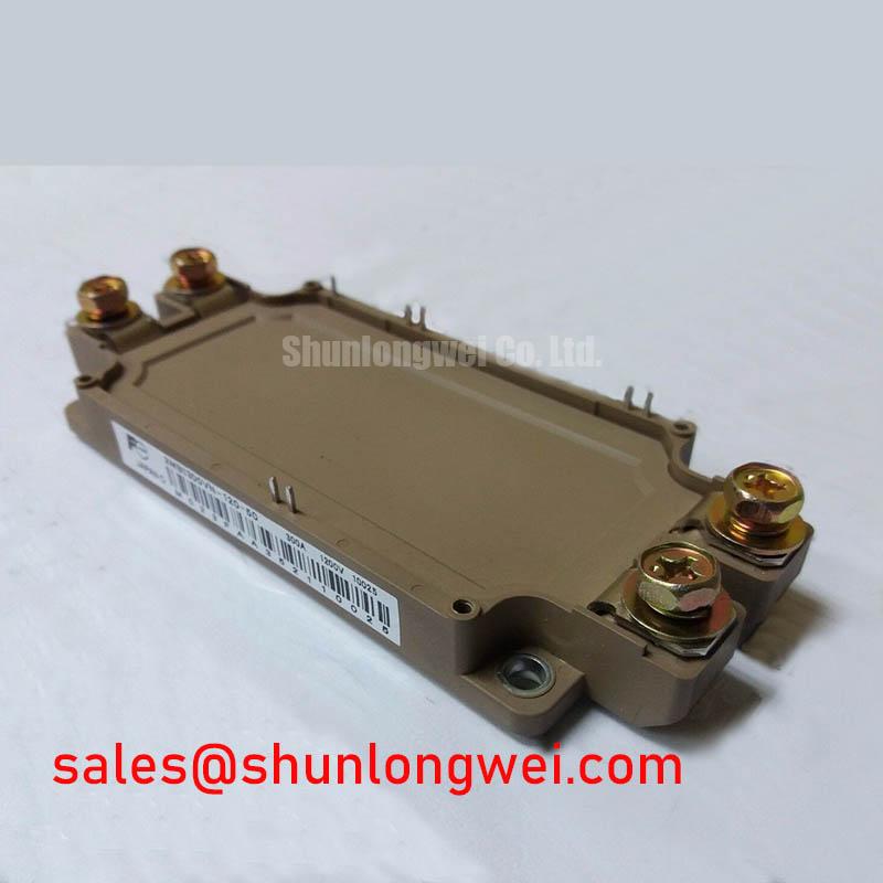
Begin the incoming inspection by confirming the marking for 2MBI300U4E-120, checking the module case for visible cracks or deformation, and recording the cold-state resistance between the power terminals and gate terminals before connecting any driver or DC source. This Fuji Electric IGBT Module is listed with an official rated voltage of 1200 V and an official rated current of 300.0 A. The listed package is Module. These values define the starting point for compatibility review; the complete application limits, switching conditions, thermal data, terminal arrangement, and protection requirements should be confirmed against the original Fuji Electric documentation available for the equipment under repair.
| Parameter | Specification status | Value |
|---|---|---|
| Manufacturer | Official product identification | Fuji Electric |
| Part number | Official product identification | 2MBI300U4E-120 |
| Rated voltage | Official Specification | 1200 V |
| Rated current | Official Specification | 300.0 A |
| Package | Official Specification | Module |
For a replacement review in a low-voltage traction inverter, do not rely on the current rating alone. Verify the electrical topology, gate-driver reference, terminal polarity, cooling interface, mechanical hole pattern, busbar clearance, and control-board timing. A module with matching headline ratings can still be unsuitable if its switching behavior, gate requirements, protection coordination, or physical connections differ from the original assembly.
💡 Bench Tip: Use ESD protection and compare all cold-state readings with a known-good reference module before applying gate-drive voltage or connecting the DC link.
Transient Dynamics and Electrical Design: DC-Link Capacitance Bank Layout and Low-ES on 2MBI300U4E-120
When evaluating the 2MBI300U4E-120 in an electric forklift or warehouse traction inverter, inspect the DC-link capacitor bank and the commutation path as one electrical loop. The module’s official voltage rating is 1200 V, so the system designer must verify that the maximum operating bus voltage, regenerative rise, switching overshoot, and protection threshold remain within the complete device and system limits. The module rating should not be treated as permission to operate at the boundary without transient testing.
A practical bench inspection starts with the positive and negative busbar route from the capacitor bank to the module terminals. Minimize the physical area of the high-current commutation loop, keep the forward and return conductors close together, and avoid routing signal wiring through the switching-current path. These are Design Considerations rather than Fuji Electric guaranteed layout specifications. The final geometry should be validated with a suitable high-bandwidth differential probe and a measurement arrangement that does not add significant loop inductance.
Switching overshoot is influenced by stray inductance and the rate of current change. In engineering terms, the peak terminal voltage rises as the parasitic inductive contribution increases during a fast current transition. This is why a compact, symmetrical planar busbar arrangement is often evaluated before adding a snubber. The target clearance, conductor thickness, capacitor technology, and mounting arrangement remain system-determined. Designers should verify the measured peak voltage at the module terminals under the intended DC-link voltage, load current, motor cable condition, and temperature.
Low-ESR capacitors may reduce high-frequency ripple, but capacitor selection cannot be separated from damping, self-resonant behavior, ripple-current capability, and physical placement. A small local film capacitor can be considered when the switching loop requires high-frequency decoupling, while the bulk bank supports lower-frequency energy movement. The correct value and technology must be calculated and tested from the actual switching waveform rather than assigned from the module current rating.
If a repaired traction controller shows repeated gate-driver or module damage, record the DC-link voltage, collector-emitter waveform, gate-emitter waveform, current rise, and turn-off overshoot at the same time. A waveform that appears acceptable at light load may change significantly during regenerative braking or rapid direction changes. Check capacitor mounting, laminated-busbar joints, loose power terminals, and the physical distance between the local capacitor and module terminals before attributing the failure to the IGBT itself.
Fuji Electric’s information on RC-IGBT Modules can help engineers understand how device family characteristics may affect a broader power-stage review. It should not be used as a substitute for the specific documentation applicable to this part number.
Transient Dynamics and Electrical Design: Isolated DC-DC Power Supply Sizing for High-Side Gate Drive
The gate-drive supply must be reviewed from the actual circuit topology rather than inferred from the 300.0 A current rating. First identify the emitter reference used by each switching position, the isolation boundary, the gate-driver output arrangement, and the required power during repetitive switching. The original controller documentation should confirm the gate voltage, gate charge, driver current, undervoltage-lockout behavior, and any negative-bias requirement. These values are not included in the supplied official product parameters and should not be guessed.
For a high-side position, an isolated DC-DC supply may be preferable to a bootstrap arrangement when duty cycle, low-speed operation, regenerative operation, or long on-time conditions make bootstrap refresh uncertain. A bootstrap circuit can be considered only after checking the required gate charge, driver quiescent current, leakage paths, switching frequency, refresh interval, and available capacitor voltage. The capacitance should be calculated from the permitted supply droop under the complete charge demand, then verified during the most demanding operating sequence.
Isolation voltage and common-mode transient immunity are properties of the selected driver and power-supply assembly, not automatic characteristics of the IGBT module. Designers should verify the reinforced isolation requirement, creepage and clearance, transformer construction, insulation system, and common-mode transient performance against the applicable equipment standard. Do not describe the module itself as having a specific isolation or CMTI rating unless that value is stated in the relevant manufacturer documentation.
At the bench, connect the gate driver to a current-limited auxiliary supply and observe the gate-emitter waveform with the power stage disabled. Check the supply at the driver pins, not only at the DC-DC converter output. Probe for droop during turn-on, ringing during turn-off, false pulses during common-mode transitions, and abnormal behavior when the control signal changes state. A clean logic signal does not prove that the isolated power rail remains stable during a high-current switching event.
Use short, controlled gate-drive and return paths, and keep them separate from the collector-emitter power loop. The gate resistor, ferrite element, Miller clamp, desaturation input, and soft-shutdown path must be selected as a coordinated network. Their final values are application-specific. When integrating a replacement module, designers should compare the gate waveform with the known-good controller and confirm that the driver does not exceed the device’s documented gate-emitter limits.
For a forklift traction system, also test low-speed creep, standstill holding, acceleration, regenerative braking, and rapid enable-disable sequences. These operating points can expose bootstrap refresh limitations or isolated-supply transients that remain hidden during a short no-load test. If the original driver board cannot be identified with confidence, the system integrator should verify the required supply voltage and timing from the original power-stage documentation.
Transient Dynamics and Electrical Design: High-Frequency Common-Mode Bearing Current on 2MBI300U4E-120
Long motor leads can create a different problem from the local DC-link loop. Fast inverter voltage transitions can couple through motor and cable capacitances to the frame, protective-earth network, encoder wiring, and motor bearings. This can produce common-mode current, electromagnetic interference, or premature bearing stress. The presence of this behavior does not by itself prove a defect in the 2MBI300U4E-120; the complete motor, cable, inverter enclosure, grounding arrangement, and switching pattern must be examined.
Start the investigation by comparing the motor-terminal waveform at the inverter and at the motor end of the cable. Use a differential probe rated for the expected common-mode environment and avoid creating an unsafe measurement return path. Check whether ringing changes with cable length, motor connection, shield termination, switching frequency, or load condition. A significant difference between the two measurement locations may indicate transmission-line behavior or impedance mismatch that requires system-level correction.
Output filters, common-mode chokes, ferrite components, and motor-side termination networks may be evaluated as Design Considerations. Their selection depends on motor insulation, cable construction, control bandwidth, leakage-current limits, enclosure bonding, and the inverter’s switching waveform. Do not assign a universal filter inductance or dv/dt limit to this module without the relevant system calculations and manufacturer data.
The power and control cables should be routed with deliberate separation, and shield termination should be reviewed at both the inverter and motor ends according to the equipment’s EMC strategy. A shield that is connected through a long pigtail may behave differently from a low-impedance circumferential termination. These are installation considerations, not a certification claim for the semiconductor module. The inverter as a complete assembly must undergo its own EMC evaluation where required.
During fault tracing, inspect the motor frame bond, inverter chassis connection, cable shield continuity, brake resistor wiring, and encoder cable routing. Use a current probe to compare common-mode current with the collector-emitter switching waveform. If the current changes after a filter is installed, confirm that the filter has not introduced excessive voltage drop, resonance, or control-loop interaction. The measured result should be checked against the motor manufacturer’s insulation and bearing guidance.
Engineers comparing switching technologies may consult the technical discussion of the Wide Bandgap Revolution for general context on high-speed power-device behavior. That material is a technology reference, not a specification for this Fuji Electric IGBT module.
Transient Dynamics and Electrical Design: High-Speed Fault Management and VCE Desaturation on 2MBI300U4E-120
Desaturation protection should be checked as a complete protection chain: sensing method, blanking interval, comparator threshold, noise filtering, driver response, soft turn-off, fault latch, and controller shutdown. The supplied official parameters identify the device as a 1200 V, 300.0 A module, but they do not establish a universal short-circuit withstand time or a guaranteed Type I or Type II protection interval. Those values must come from the applicable Fuji Electric technical documentation and the selected gate-driver data.
A practical test begins with the power stage disabled and a simulated fault signal applied to the protection input. Confirm that the driver detects the programmed condition, blocks the next command, reports the fault to the controller, and discharges or clamps the gate according to the intended design. After that low-energy test, perform controlled switching tests with suitable current limiting and protection. Measure the collector-emitter voltage, gate-emitter voltage, fault signal, driver output, and DC-link voltage on a common time base.
Soft turn-off is commonly considered because abruptly removing gate current during a high-current fault can increase inductive voltage stress. A two-stage strategy may use an initial controlled gate-current reduction followed by a stronger shutdown action, but the timing and gate levels are system-determined. The design team must verify that the method limits peak voltage without prolonging the fault current beyond the module’s documented safe operating area.
False desaturation trips can result from probe layout, parasitic inductance, excessive noise, an unsuitable blanking arrangement, or an incorrect reference connection. Conversely, a delayed response may leave the module exposed to excessive current. Compare the protection waveform with a known-good inverter and inspect the desaturation diode path, gate loop, auxiliary supply stability, and isolation barrier. Do not diagnose a module failure from a single fault waveform without checking the driver and measurement circuit.
Fuji Electric’s reference material on Brake Chopper IGBT Modules provides useful background for engineers reviewing braking-energy paths, but the protection settings for this module must be established from the correct part-specific documentation. For an objective cross-reference during procurement or repair assessment, the 2MBI150UC-120 may be reviewed as a separate Fuji Electric product; electrical, mechanical, thermal, and gate-drive compatibility must be verified before any substitution is considered.
Before releasing the repaired traction inverter, confirm terminal polarity, insulation condition, gate-driver behavior, cooling contact, DC-link precharge operation, regenerative braking response, and fault shutdown under controlled test conditions. The system integrator remains responsible for validating operating margins against the actual forklift controller, motor, battery voltage, cable arrangement, and protective functions.