
Content last revised on September 10, 2026
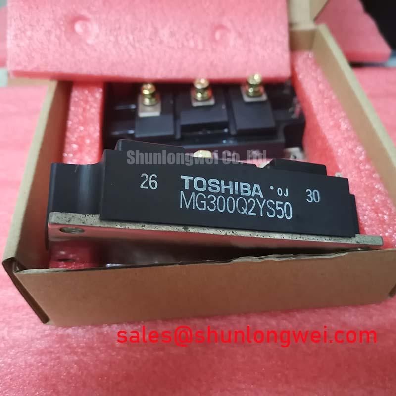
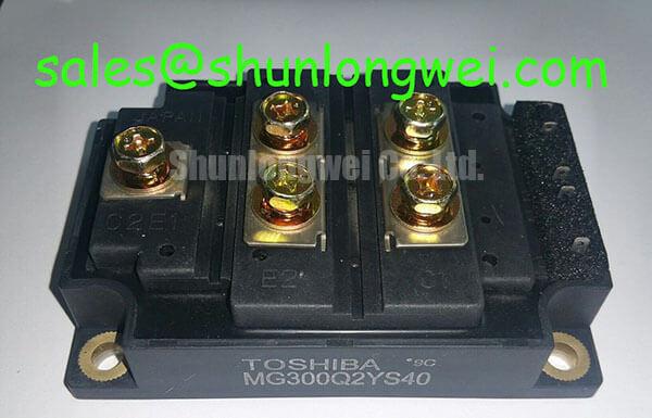
Toshiba MG300Q2YS40 600V 300A Dual IGBT Module for High-Speed Switching
The Toshiba MG300Q2YS40, a cornerstone of the G-Series power modules, is an N-channel enhancement mode IGBT Module designed specifically for high-power, high-speed switching applications. Engineered to optimize power density in medium-voltage inverter stages, it leverages a half-bridge configuration to minimize switching transients and maximize thermal efficiency. This module delivers a robust 600V collector-emitter voltage and a 300A continuous collector current, making it a reliable choice for industrial motor drives and power conversion systems. Its optimized internal chip structure significantly reduces tail current, effectively minimizing turn-off losses and allowing for higher switching frequencies without excessive heat generation. For 400V inverter designs prioritizing high-speed switching efficiency and thermal margin, the MG300Q2YS40 provides a robust, low-loss solution.
Application Scenarios & Value
Achieving System-Level Efficiency in High-Frequency Power Conversion
Engineers often face the critical challenge of balancing switching speed with thermal dissipation in Variable Frequency Drive (VFD) designs. In high-current industrial environments, the MG300Q2YS40 addresses this by providing a low VCE(sat) (typically 2.1V), which reduces conduction losses during the "on" state. When managing "industrial conveyor systems," the high pulse current handling capability of this module ensures it can withstand the significant motor startup surge currents without entering desaturation. For systems requiring lower power footprints, the MG150Q2YS50 may be considered, whereas for 600V systems needing even higher current overhead, the MG400Q2YS60A offers an alternative power profile.
This module is extensively utilized in Uninterruptible Power Supply (UPS) systems and high-capacity AC/DC inverters. By integrating a Fast Recovery Diode (FRD) within the package, the MG300Q2YS40 simplifies the circuit layout by eliminating the need for external anti-parallel diodes, thereby reducing parasitic inductance in the power loop. This integration is vital for meeting IEC 61800-3 EMC standards, as it dampens voltage overshoots during high-speed switching transitions.
Technical Deep Dive
Analyzing N-Channel Enhancement Mode and Thermal Conductivity
The internal architecture of the MG300Q2YS40 utilizes an enhancement-mode structure, which ensures the device remains in a non-conductive "fail-safe" state if gate drive power is lost. This is a critical safety feature in high-power Servo Drive applications where unintended motor movement could lead to catastrophic failure. To understand the physical robustness of these switches, one might refer to a deep dive into IGBT modules to see how the silicon die is bonded to the ceramic substrate to facilitate heat transfer.
The switching speed of this IGBT Module is comparable to a high-performance mechanical relay that moves without the physical lag of mass, allowing it to toggle thousands of times per second with negligible wear. However, at these speeds, the Thermal Resistance (Rth(j-c)) becomes the limiting factor. The MG300Q2YS40 features a highly isolated baseplate, which acts as a thermal highway, ensuring that heat generated at the junction is moved rapidly to the heatsink. This efficiency is what allows the module to maintain a stable Short-Circuit Safe Operating Area (SCSOA), providing the 10-microsecond withstand time necessary for protection circuits to react during a fault condition. Engineers can further validate these parameters by learning how to test an IGBT module during the prototyping phase.
Key Parameter Overview
Decoding the Specs for Enhanced System Reliability
| Technical Specification | Value / Rating | Engineering Significance |
|---|---|---|
| Collector-Emitter Voltage (VCES) | 600V | Provides adequate voltage margin for 240V/380V AC line rectified DC buses. |
| Collector Current (IC) | 300A | Supports heavy-duty industrial loads and high-torque motor applications. |
| Collector-Emitter Saturation Voltage | 2.7V (Max) | Directly dictates conduction losses; lower values enable higher system efficiency. |
| Fall Time (tf) | 0.3µs (Typ) | Ultra-fast transition reduces switching energy loss (Eoff) during turn-off. |
| Isolation Voltage (Visol) | 2500V AC | Ensures safety and signal integrity between the power stage and control logic. |
Download the MG300Q2YS40 datasheet for detailed specifications and performance curves.
Frequently Asked Questions
How does the 300A rating impact the busbar design for the MG300Q2YS40?
The 300A continuous current requires a low-inductance laminated busbar to prevent voltage spikes ($V = L cdot di/dt$) during the high-speed turn-off transitions characteristic of this module. Proper busbar sizing also ensures that terminal temperatures remain within the 150°C maximum junction limit.
What are the specific gate drive requirements for this Toshiba module?
The MG300Q2YS40 requires a gate-emitter voltage ($V_{GE}$) of 15V for full conduction. It is recommended to use a Negative Gate Voltage (-5V to -9V) during the off-state to prevent parasitic turn-on caused by the Miller effect in high $dv/dt$ environments.
Does the 600V VCES provide enough margin for 480V AC systems?
Typically, no. For a 480V AC system, the peak rectified DC link voltage can exceed 670V. For such applications, a module with a 1200V $V_{CES}$ is required. The MG300Q2YS40 is optimized for 200V-240V AC input systems where the DC bus typically sits around 310V-340V.
Why is the Fall Time (tf) of 0.3µs significant for inverter design?
A shorter Fall Time reduces the overlap between decreasing current and increasing voltage during turn-off. This minimizes the "switching tail," which is the primary source of heat in high-frequency pulse-width modulation (PWM) applications.
What precautions should be taken regarding the isolation voltage?
With an Isolation Voltage of 2500V, the module allows for the mounting of multiple units on a single grounded heatsink. However, engineers must ensure that creepage and clearance distances on the PCB and around the terminals are maintained according to industrial safety standards to prevent arcing.
When integrating the MG300Q2YS40 into new designs, engineers should prioritize the minimization of stray inductance in the gate drive loop to prevent oscillations. Utilizing a Kelvin Emitter connection, if supported by the driver layout, will significantly improve switching accuracy. For long-term field reliability, ensuring that the thermal interface material is applied with uniform pressure is as critical as the electrical timing itself.