Content last revised on September 28, 2026
CM300DU-12F Circuit Protection and Heatsink Contact
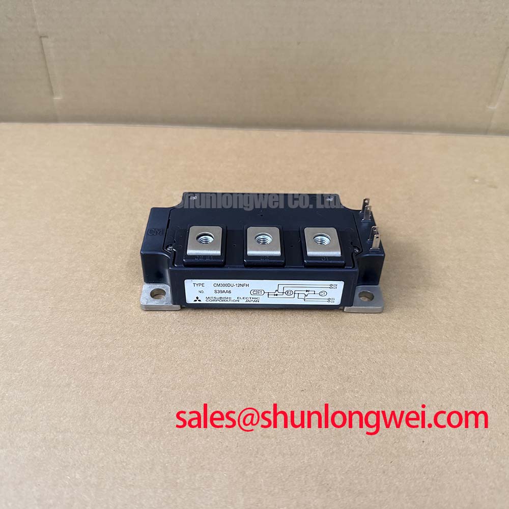
With the DC link discharged and the module isolated, check the terminal markings against the equipment schematic before measuring cold terminal resistance. The CM300DU-12F is a Mitsubishi Electric IGBT module rated at 600 V and 300 A (Official Specifications); its stated package is Module (Official Specification). These ratings identify the part, but they do not establish its terminal arrangement, mounting dimensions, or suitability for a particular inverter without the original device documentation.
At incoming inspection, compare resistance measurements across equivalent terminal paths with a documented, known-good unit where one is available. A multimeter diode-mode check can help examine a diode path only after its terminals and polarity have been confirmed from the module drawing. Record the meter range and probe direction: an unexplained difference calls for further investigation, not an immediate diagnosis of a failed chip.
💡 Bench Tip: Discharge the DC link and protect the gate terminals from electrostatic handling before connecting test probes.
For mounting, a Design Consideration is to clean the mating surfaces, apply thermal interface material as a thin, continuous layer, and inspect for trapped air or uneven contact. Bring mounting screws up progressively in a balanced sequence rather than drawing one corner down first. Baseplate shape, heatsink flatness, interface material, and the specified fastening procedure all affect contact pressure; verify torque and any permitted surface tolerances against the applicable module and equipment instructions. Do not treat a generic grease thickness or screw torque as a CM300DU-12F factory limit.
Insulation assessment also needs the original device documentation and the equipment test procedure. Compare the required clearance and insulation test conditions with the assembly drawing before applying a withstand test; a 600 V switching-device rating is not, by itself, an insulation withstand rating. Mitsubishi Electric’s power semiconductor documentation provides a manufacturer starting point for locating device-specific technical material.
Field Diagnostics and Peak Junction Temperature
When a repaired power stage runs hot under pulsed load, start with measurements the technician can repeat: case or heatsink temperature at a defined location, DC-link voltage, load current, pulse duration, and cooling conditions. A warm heatsink does not disclose peak junction temperature during a short overload. An Engineering Calculation using the device’s documented transient thermal impedance and measured loss waveform can estimate that peak; without the relevant thermal curve and loss data, a numerical junction-temperature margin would be speculative.
Switching frequency changes the balance between conduction and switching losses, while airflow and ambient temperature affect the temperature from which each pulse begins. Designers should evaluate those conditions over the equipment’s actual duty cycle rather than apply a universal derating figure. If temperatures differ between otherwise comparable assemblies, inspect fan operation, interface contact, fastening, and the measurement location before assigning a cause.
For long-running equipment, the maintenance question is whether measured operating conditions remain inside documented limits, not whether a component has a presumed service-life figure. The broader Industrial Applications discussion can provide context for duty-cycle evaluation; it does not replace CM300DU-12F thermal data. An industrial inverter welder or medium-frequency induction-heating supply is a possible compatibility review case, subject to its circuit and cooling requirements.
Transient Dynamics and Parallel Current Sharing
For parallel CM300DU-12F positions, record cold terminal readings separately and trace each gate and power connection back to the schematic. Static current balance depends on device characteristics and the operating point; a positive temperature coefficient of on-state voltage must not be assumed across the entire current range. Consult the relevant characteristic curves before relying on temperature-related self-balancing.
Dynamic imbalance requires a different check. As a Design Consideration, keep corresponding gate-drive paths and power-loop geometry comparable, then measure switching waveforms at representative operating conditions. A current difference may reflect wiring, gate-drive behavior, thermal contact, or device variation; compare the traces and physical paths before changing components.
Protection should be assessed as a system function. Where the equipment uses desaturation detection and soft turn-off, verify detection behavior, driver response, and switching stress against the original driver design and the module’s documented limits. Neither the 300 A rating nor a cold diode-mode result establishes a short-circuit safe operating area. Mitsubishi Electric’s semiconductor resources are relevant when checking available manufacturer characteristics and application guidance.
CM300DU-12F Busbar Geometry and Switching Overshoot
At turn-off, stray inductance in the commutation path adds voltage overshoot to the DC-link voltage. As an Engineering Calculation, the first-order relationship expresses peak voltage as DC-link voltage plus loop inductance multiplied by current slew rate; actual waveforms also depend on switching behavior and any clamping network. Keep the outgoing and return current paths close and geometrically balanced as a Design Consideration, then verify measured peaks against the module’s 600 V rating under the equipment’s worst relevant operating conditions.
A snubber cannot be sized responsibly from the module voltage rating alone. Measure the switching-node waveform with an appropriate probe arrangement, review the busbar and capacitor connections, and assess the resulting voltage and thermal stress after any layout or snubber change. For a repair parts comparison, CM300DXDX1-24A can be placed on the review list, but its terminal layout, electrical ratings, mounting, and switching characteristics must be checked independently; a similar model designation does not establish interchangeability.