Content last revised on October 24, 2026
CM800E2C-66H Ratings and Pre-Service Checks
- Verify that the DC link is isolated and fully discharged before touching the power terminals or gate circuit.
- Record cold-state terminal and antiparallel diode readings with a digital multimeter in diode-check mode.
- Inspect the heatsink interface, thermal compound condition, mounting flatness, and airflow path before energizing the replacement.
- Check gate-emitter insulation using a gate-safe test method and inspect the physical separation of power, gate, and sensing conductors.
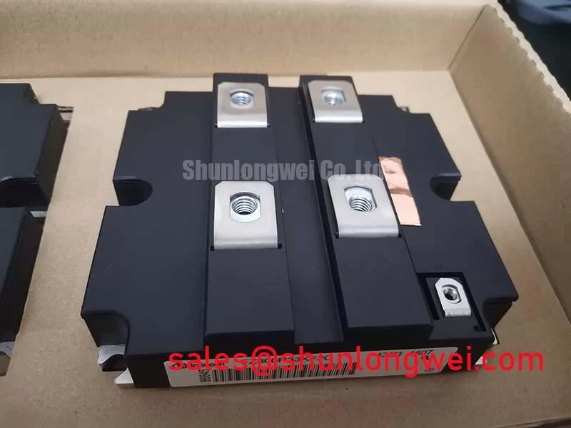
The Mitsubishi Electric CM800E2C-66H is a high-voltage, high-current IGBT module intended for demanding converter and inverter platforms. Its official ratings include a 3300 V collector-emitter voltage, 800 A collector current at Tc = 95°C, and a 1600 A peak collector current under the specified pulse conditions. The module may be evaluated for high-power conversion equipment such as utility-scale centralized battery energy storage PCS systems, subject to the complete electrical, thermal, and protection design.
| Manufacturer | Mitsubishi Electric |
| Model | CM800E2C-66H |
| Collector-emitter voltage VCES | 3300 V, Official Datasheet Specification |
| Collector current IC | 800 A at Tc = 95°C, Official Datasheet Specification |
| Peak collector current ICM | 1600 A under the datasheet pulse conditions |
| Maximum power dissipation Pc | 9.6 kW under the datasheet thermal conditions |
| Collector-emitter saturation voltage VCE(sat) | 3.8 V typical at IC = 800 A, subject to the datasheet gate-voltage and temperature conditions |
| Maximum junction temperature Tj max | 150°C, Official Datasheet Specification |
| Thermal resistance Rth(j-c) | 0.013 K/W for the IGBT, Official Datasheet Specification |
| Isolation voltage Viso | 6000 Vrms under the datasheet isolation-test conditions |
CM800E2C-66H Operational Boundaries: Evaluating High-Speed Fuse Arcing Voltage Limits
Protection coordination must be assessed at the moment a DC-link fault develops, not only from the normal operating current. Fast electronic protection must limit IGBT fault stress within the device’s documented capability; a semiconductor fuse provides coordinated fault interruption but cannot be assumed to act quickly enough to prevent IGBT damage. The module installation must also account for the fuse’s arcing voltage and resulting transients within the available insulation and device voltage margins. The relevant fuse characteristic is its total clearing I2t, including both pre-arcing and arcing contributions. Fuse selection must also account for its DC voltage rating, circuit time constant, and the actual prospective short-circuit conditions.
For a centralized battery PCS, the battery rack, busbar arrangement, DC-link capacitor bank, contactor structure, and inverter bridge all influence fault energy. A fuse that appears suitable from its continuous current rating may not provide the required sub-cycle interruption behavior when the battery source has low impedance. Engineers should assess electronic protection against any documented module short-circuit limits and evaluate fuse clearing against the fault withstand requirements of the protected circuit. Peak collector-emitter voltage should also be verified during controlled switching tests.
Physical layout is part of the protection system. Keep the high-current commutation loop compact, route forward and return conductors with controlled coupling, and separate gate wiring from the high dV/dt power path. The cabinet should also preserve the creepage and clearance required by the working voltage, pollution environment, and insulation system. These are Design Considerations rather than independent certification claims for the module.
When a fuse has operated, inspect the module terminals, busbar faces, fuse holders, and nearby insulation for evidence of arc tracking or localized heating. A replacement should not be energized until the fault cause, fuse coordination, and gate-driver condition have been reviewed. Avalanche multiplication and impact ionization are useful physical concepts when assessing high-voltage transient stress, but they do not establish an avalanche operating capability for this module. An accessible technical reference is Impact Ionization and Avalanche Multiplication in High Voltage PN Junctions.
Transient Dynamics & Electrical Design: Diagnosing Latent Gate-Emitter Dielectric Faults on CM800E2C-66H
Cold, unpowered screening should begin with the main terminals and antiparallel diode, followed by a controlled check of the gate-emitter paths. Use the digital multimeter diode-check function only after the module is isolated from the driver, DC-link capacitors, snubber network, and sensing circuits. Keep the gate-emitter voltage controlled during main-terminal checks so that a floating gate does not turn the IGBT on and distort the readings. Compare readings across corresponding channels where the internal topology permits a meaningful comparison. A strong asymmetry may indicate a damaged semiconductor path or contamination around the terminals; confirm that no external parallel path remains before drawing a device-level conclusion.
Gate leakage deserves separate attention because a gate-emitter dielectric fault may remain hidden during a simple collector-emitter check. Measure the gate circuit with the correct polarity and instrument limits, avoiding any test voltage that exceeds the gate rating stated in the applicable Mitsubishi Electric documentation. Check the driver output resistor, gate clamp, isolation barrier, and return path at the same time. A failed driver component can reproduce symptoms that resemble module damage.
Switching transients are strongly affected by Miller plateau behavior and the effective gate loop inductance. Collector-gate capacitance, represented by Cres, couples current into the gate circuit during fast collector-voltage transitions. This is why gate resistance, clamp behavior, driver sink capability, and the physical return path must be evaluated as one system. Selective adjustment is an Engineering Recommendation based on measured switching waveforms, not a fixed value for this module.
The fuse and semiconductor protection network must also be checked after any gate fault. A defective gate drive can leave the IGBT partially enhanced, increasing dissipation while the fuse remains intact. Review the timing of desaturation or overcurrent protection, the isolation barrier response, and the fuse’s total clearing I2t under the real battery source impedance. The CM450DX-24S1 may be considered separately in converter front-end studies, but its suitability depends on the complete schematic, voltage class, current path, and control strategy.
Assembly Integrity & Layout Architecture: Managing High-C-Rate Battery Cycling with CM800E2C-66H
Four-quadrant PCS operation includes bidirectional active-power flow between the battery racks and the AC grid, together with reactive-power control. During charging, discharging, reactive-power support, and transition events, the CM800E2C-66H can experience changing conduction and switching losses. The official 9.6 kW maximum power dissipation under the datasheet thermal conditions and 0.013 K/W IGBT junction-to-case thermal resistance provide important device-level boundaries, but the usable operating point remains dependent on the heatsink, interface material, coolant or airflow, switching conditions, and control duty.
Thermal maintenance should focus on trend changes rather than a single temperature snapshot. Record phase-to-phase temperature behavior during comparable load cycles and inspect the heatsink for blocked fins, fan degradation, dust accumulation, or uneven contact. Thermal interface material can dry, pump out, or develop voids after repeated temperature cycling. Remove the module only under the approved maintenance procedure, clean both mating surfaces without damaging them, and apply the selected interface material according to the system manufacturer’s process.
Busbar geometry should support a low-inductance commutation path while preserving the required insulation spacing. Avoid routing the gate return alongside a high-current switching conductor for long distances. Use mechanical support so that terminal weight, vibration, or repeated thermal expansion does not transfer excessive force into the module connection points. Fastener torque is a Design Consideration determined by the module and system assembly instructions, not an assumed universal value.
Maintenance Note: Monitor contact temperature and verify the cooling airflow during scheduled service, because a gradual rise under the same load can indicate interface aging, blocked ventilation, or connection resistance.
For cross-reference work, engineers may review the comparison of CM1500HC-66R with another Mitsubishi Electric module family. Such a comparison should be treated as a technical screening aid; voltage class, current duty, package geometry, pin arrangement, gate-drive requirements, and protection behavior must be matched before any substitution is considered.
Field Diagnostics & Commissioning: Screening for Substrate Insulation Damage in CM800E2C-66H Installations
Isolation testing should be performed after the module has been disconnected from the inverter, snubbers, sensors, gate driver, and any parallel protection components. The specified module isolation voltage is 6000 Vrms under the datasheet test conditions, while a field insulation-resistance test is a separate commissioning activity. Use only the test voltage and acceptance criterion specified by the equipment or module manufacturer’s applicable procedure; the factory isolation rating does not by itself authorize a particular field test.
Follow the manufacturer’s approved terminal connections for testing between the module’s electrical circuit and baseplate, including any required bonding of power and gate terminals to prevent differential stress across the semiconductors. Use the test duration and discharge procedure defined by the applicable test procedure. Record the result, ambient humidity, surface cleanliness, and test configuration. Dust, moisture films, flux residue, and condensation can produce leakage paths that resemble a substrate problem. If the reading changes significantly after controlled cleaning and drying, investigate contamination and enclosure conditions before attributing the result to internal ceramic damage.
Visible inspection should include the baseplate edge, terminal surrounds, mounting surface, and areas exposed to mechanical stress. A ceramic substrate crack may not be visible from the outside and cannot be confirmed by appearance alone. When isolation declines after thermal cycling, compare the result with a known-good measurement configuration and inspect for distortion, uneven mounting pressure, or contamination around the insulation path.
High-altitude installations introduce additional Design Considerations involving reduced air insulation capability and increased exposure to cosmic-ray-induced stress. FIT, single-event burnout, and altitude derating values require a defined device technology source, mission profile, and reliability method; they should not be inferred from the voltage rating alone. For resonant or soft-switching converter studies, the engineering discussion in Resonant Topologies in Home Appliances can provide useful topology context, although the actual PCS switching network must be assessed from its own schematic and measured waveforms.