

Content last revised on November 5, 2026
CM600DU-24FA Incoming Inspection and Rating Review
- Isolate the DC link, verify discharge, and compare the module terminal markings with the equipment schematic before connecting test leads.
- Check collector–emitter diode polarity with a low energy meter test, keeping each gate referenced to its corresponding emitter.
- Inspect the mounting surface, terminal seating, and gate connections for contamination, distortion, or mechanical loading.
- Compare the equipment’s electrical requirements with the 1200 V collector–emitter rating and 600 A collector current rating under the specified datasheet conditions.
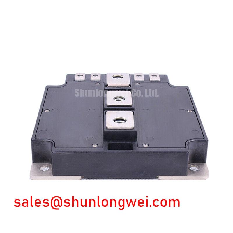
The CM600DU-24FA is a Mitsubishi Electric IGBT module with a dual configuration forming a half bridge. Incoming inspection should establish terminal consistency and a repeatable cold measurement baseline before powered evaluation. A diode mode reading depends on meter test current, temperature, and connected circuitry; it is useful for comparison, but does not establish switching performance or full current capability.
| Parameter | Official Specification |
|---|---|
| Manufacturer | Mitsubishi Electric |
| Part number | CM600DU-24FA |
| Product category | IGBT Module |
| Collector–emitter voltage, VCES | 1200 V |
| Collector current, IC | 600 A; consult the datasheet for rating conditions. |
| Configuration | Dual IGBT half bridge |
| Package | Module |
| Additional acceptance limits | Consult Datasheet for rating conditions, terminal drawing, insulation test conditions, thermal limits, and fastening requirements. |
💡 Bench Tip: Keep the gate referenced to its emitter during cold diode checks and use ESD controlled handling so that retained gate charge does not distort the comparison.
Benchtop Waveform Review: High-Altitude Cosmic Ray Induced SEB Risk for CM600DU-24FA
Record the intended installation altitude and the highest sustained blocking voltage before reviewing an altitude related reliability requirement. As a Design Consideration, atmospheric neutron exposure can contribute to single event burnout in susceptible power semiconductors. Its relevance depends on device characteristics, blocking voltage, and the installation environment; an oscilloscope trace alone cannot quantify that exposure.
Keep the bench investigation focused on measurable electrical stress. Capture collector–emitter voltage during blocking intervals and switching transitions, using appropriately rated differential measurement equipment. Record DC link variation, overshoot, and operating temperature alongside the waveform. These measurements define the electrical conditions that a device specific reliability assessment would need, without assigning a failure rate to an unexplained event.
An engineering FIT calculation requires a manufacturer supported susceptibility model or applicable test results, combined with the relevant environmental exposure. A generic altitude correction or a percentage reduction from 1200 V does not establish a CM600DU-24FA reliability limit. Where altitude is a procurement requirement, request the applicable device assessment through the Mitsubishi Electric Power Semiconductors & High-Power Modules resource and use it within the equipment reliability review.
The Mitsubishi Electric High-Voltage HVIGBT Modules resource concerns a separate product grouping; its ratings and reliability information should not be transferred to this module. On the bench, preserve failed device observations, protection records, and voltage captures rather than attributing damage to cosmic radiation from appearance alone.
Transient Dynamics & Electrical Design: Protection Coordination for CM600DU-24FA
Separate gate controlled short circuit protection from fuse interruption when reviewing the CM600DU-24FA fault path. As a Design Consideration, semiconductor fuse total clearing I²t is the integral of current squared over the interruption time under specified conditions. An IGBT short circuit withstand characteristic describes a different operating event, with defined gate drive, voltage, temperature, and timing conditions.
Those quantities cannot be compared as interchangeable survival ratings. Assess the prospective fault current, DC interruption capability, circuit inductance, fuse operating characteristics, and the driver’s detection and shutdown sequence together. Module case containment requires coordinated assembly evidence; selecting a fuse by nominal current or I²t alone does not demonstrate protection against case rupture.
Type 2 coordination has a defined role in motor starter coordination under IEC 60947-4-1. Applying that phrase to an inverter power stage does not establish an equivalent IGBT protection classification. For equipment acceptance, use the protection requirements and test evidence applicable to the actual converter assembly.
Terminal verification should trace the DC positive connection, switching midpoint, DC negative connection, and individual gate–emitter pairs through the manufacturer drawing and equipment schematic. For cold checks, isolate parallel circuit paths that could influence the meter reading. Compare equivalent diode paths under matching conditions; an unusual result calls for further isolation and inspection rather than an immediate diagnosis.
For layout acceptance, evaluate creepage and clearance against working voltage, insulation materials, contamination conditions, and the equipment standard. Check busbar alignment before tightening so that fasteners do not pull terminals into position. Use the documented fastening and retention method for the assembly’s vibration environment.
Replacement review also requires topology and interface checks. The CM35MXA-24S can be included in a broader component comparison, but no drop in replacement relationship is established here. Likewise, any CM30TF-24H considered elsewhere in a power assembly needs its own circuit role assessment; its designation does not identify it as a front end rectifier.
Transient Dynamics & Electrical Design: Turn-Off di/dt Induced Voltage Overshoot on CM600DU-24FA
Measure turn off voltage at the module terminals before changing gate resistance or adding a snubber. Probe connection geometry and instrument bandwidth affect the observed ringing, so retain the same measurement arrangement when comparing revisions.
As an Engineering Calculation, the approximate inductive contribution follows Vpeak ≈ VDC + Lσ|di/dt|. This simplified relationship connects commutation loop inductance and current fall rate to voltage overshoot; diode recovery, capacitance, and ringing also influence the measured waveform. It supports an investigation, rather than supplying a universal snubber value or busbar inductance target.
As a Design Consideration, reduce commutation loop area and place the local DC link connection so that outgoing and returning current paths remain close. Preserve insulation distances while evaluating the busbar geometry. A snubber assessment should account for pulse energy, voltage rating, heating, and the complete transient response, with component selection determined by system measurements.
Trace gate drive return current separately from the main emitter current wherever the documented terminal arrangement supports that routing. Do not infer a dedicated Kelvin emitter terminal from package appearance. Shared emitter inductance can alter the effective gate voltage, making the return path relevant to both switching stress and protection behavior. The Precision Gate Drive Design guide provides related integration context.
If modules operate in parallel, compare branch current during steady conduction and switching transitions. Static sharing does not establish dynamic sharing, and a favorable temperature coefficient should not be assumed without the applicable characteristic curves. For any system using bootstrap gate supplies, assess charge availability across its actual duty cycle and startup sequence, including diode recovery effects; bootstrap circuitry is a system design choice, not a stated feature of this module.
Assembly Integrity & Layout Architecture: Heatsink Contact and Mounting for CM600DU-24FA
Inspect heatsink flatness, cleanliness, and mounting hole alignment before applying thermal interface material. As a Design Consideration, the interface should fill surface irregularities while avoiding unnecessary thermal resistance. Select the material and application process against the module mounting instructions and the heatsink’s documented surface condition.
Control coverage through a repeatable application method and inspect the contact pattern during process qualification. Material squeezed beyond the baseplate edge does not demonstrate complete contact underneath it. Do not compensate for surface distortion by adding grease or increasing screw torque; assess baseplate and heatsink geometry against the permitted mechanical limits.
Seat the module without lateral force, then follow the specified tightening sequence and torque with a calibrated tool. Support busbars independently so that their weight and thermal movement do not load the power terminals. After assembly, compare temperatures at equivalent operating conditions and investigate uneven heating through interface contact, cooling performance, electrical loading, and measurement placement.
For a multi megawatt offshore or onshore wind turbine full scale converter, compatibility assessment should include the converter topology, branch loading, cooling arrangement, protection system, and mechanical interface. The 1200 V, 600 A ratings alone do not establish suitability for that equipment. During a replacement review, match the complete part designation and terminal drawing, then retain the mounting inspection and cold test records with the equipment service documentation.