

Content last revised on October 6, 2026
AUO G121SN01 V0 Industrial LCD Module Inspection and Integration
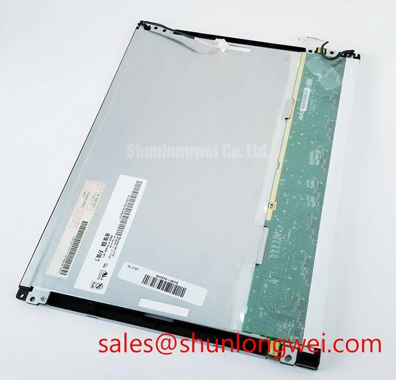
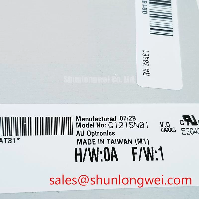
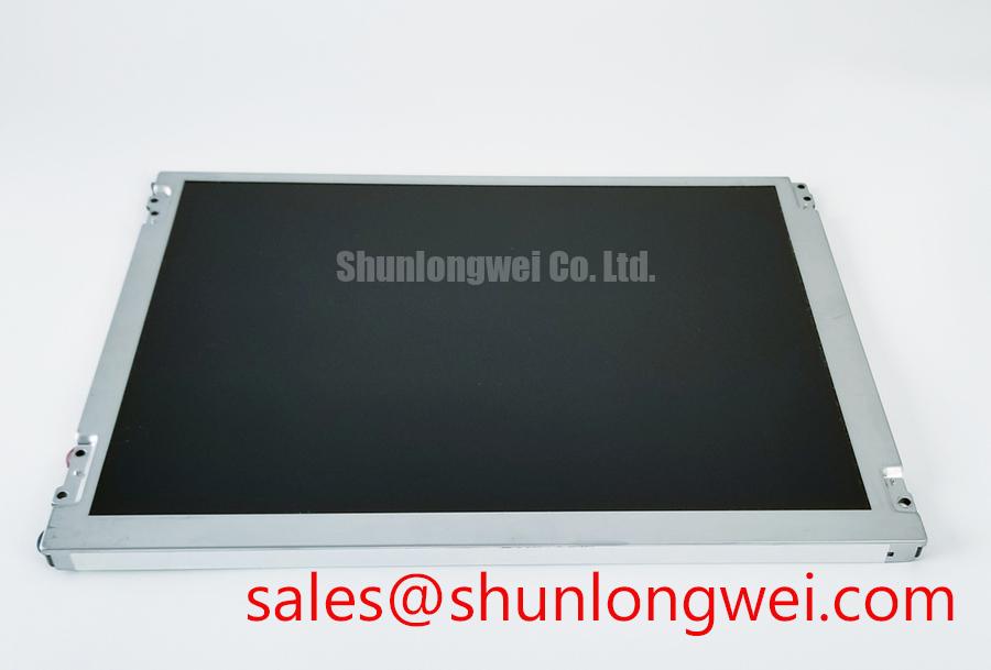
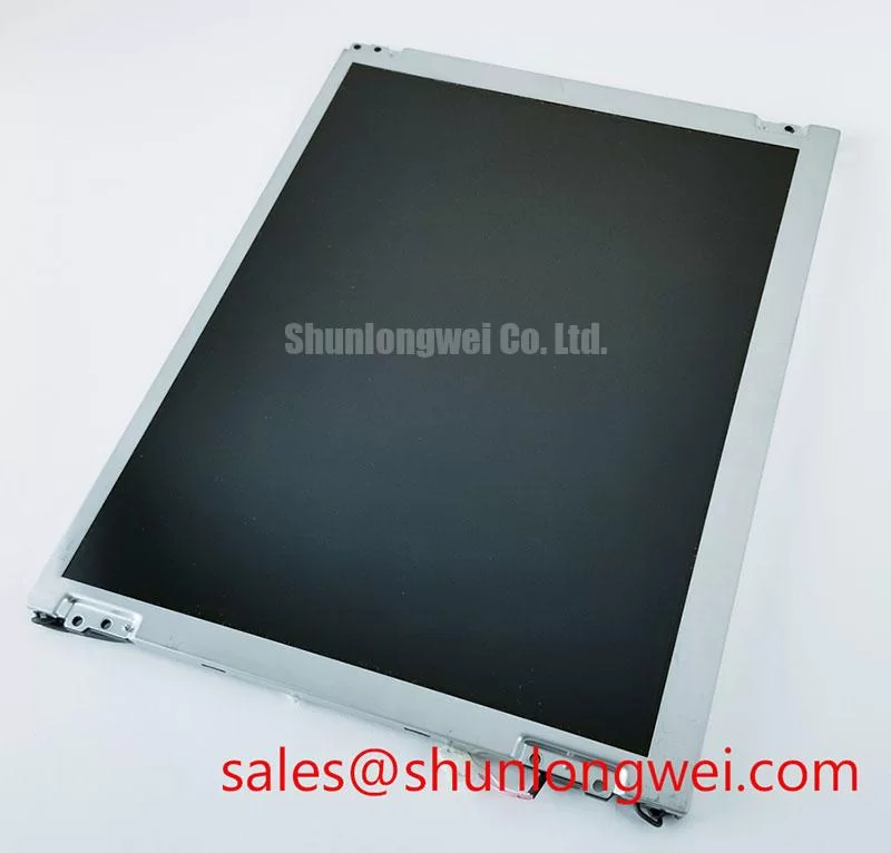
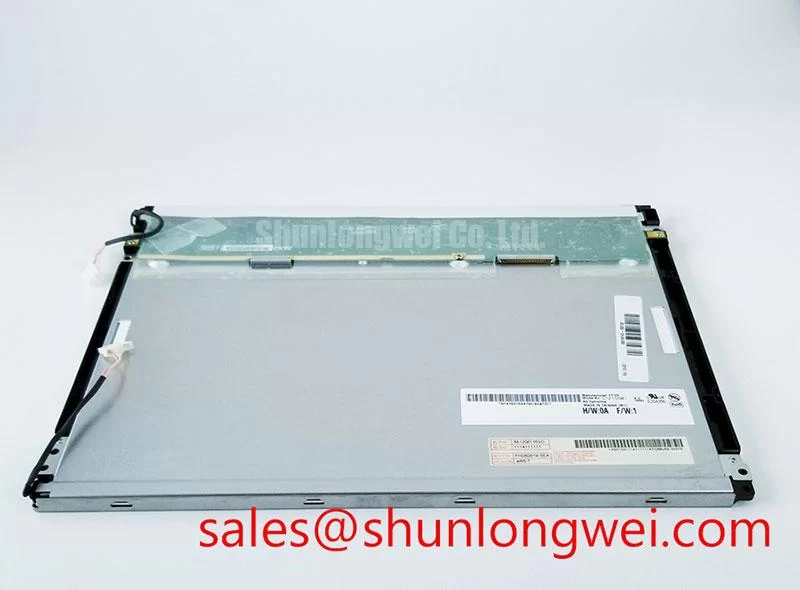
Begin the service inspection by comparing the replacement panel’s identification label with the original assembly and checking the connector, bezel, and visible glass area for handling damage before applying power. The G121SN01 V0 is an AUO TFT LCD Display Module classified for industrial HMI use, with its supplied product information marked Official Factory Spec Verified. Its documented product category is an Industrial Grade LCD/HMI Panel; the enclosure format is a TFT-LCD Display Module.
This product page intentionally separates confirmed factory information from system-level integration considerations. The supplied factory data does not confirm panel dimensions, native resolution, luminance, viewing technology, interface pin assignment, supply voltage, backlight construction, response time, or operating-temperature limits. The original equipment documentation must therefore remain the controlling reference for those values. This is particularly important when evaluating a replacement for a CNC operator panel or robot teach pendant, where mechanical fit and display timing must be confirmed together.
| Item | Confirmed information |
|---|---|
| Model | G121SN01 V0 |
| Manufacturer | AUO |
| Product category | Industrial Grade LCD/HMI Panel |
| Module format | TFT-LCD Display Module |
| Specification status | Official Factory Spec Verified |
| Typical evaluation context | Industrial HMI, CNC operator panel, or robot teach pendant, subject to system compatibility verification |
Flush-Mount Open-Frame Bezel Integration and Perimeter Gasket Shock Isolation
Before removing the failed display, record the existing cutout, bezel overlap, connector approach, cable bend direction, and gasket contact pattern. The G121SN01 V0 is identified as a TFT-LCD display module rather than a complete operator-panel assembly, so the mounting frame, sealing method, protective window, and compression hardware are determined by the host equipment. Designers should verify the original mechanical drawing instead of assuming that a panel with a similar diagonal or electrical interface will share the same bezel envelope.
A flush-mounted CNC control panel needs even support around the display perimeter. A gasket can help isolate vibration, prevent dust migration, and reduce direct frame-to-glass contact, but its material, profile, compression, and environmental rating must be selected by the system integrator. The gasket should contact the intended bezel or carrier surface continuously without pressing on active viewing areas. Uneven fastener loading can distort the module or create visible optical non-uniformity, so tightening should follow a cross-pattern with the final torque controlled by the display frame and fastener specification. The commonly referenced M3 range of 0.35 to 0.45 N·m is a general installation consideration only, not a confirmed AUO factory requirement for this model.
Check the mounting rails for burrs, warped sheet metal, trapped cable sections, and hard particles beneath the perimeter seal. In a robot teach pendant, repeated hand movement and cable flexing can transfer mechanical stress into the display carrier. The panel should be supported by the intended chassis structure rather than by the signal cable or backlight lead. If an optical bonding layer, cover lens, or sealing compound is part of the existing assembly, its compatibility with the replacement module should be verified from the host equipment documentation; no bonding construction is confirmed in the supplied specification.
Long-term optical stability also depends on heat distribution. A backlight type, rated luminance, and service-life curve are not provided in the confirmed data for the G121SN01 V0. Do not assign a 50,000-hour or half-brightness value to this model without the applicable AUO document. During acceptance testing, inspect the display at low, medium, and high brightness settings and compare uniform fields with a known-good unit. Changes may originate in the display, driver, optical stack, or enclosure airflow, so the complete assembly should be evaluated.
Maintenance Note: Isolate power before disconnecting the panel and periodically inspect the perimeter gasket, ventilation path, and cable strain relief for dust ingress or mechanical loading.
20-Pin or 30-Pin Differential LVDS Timing, Pixel Clock, and Skew Compensation
Connector count alone is not sufficient to identify compatibility. A replacement review should compare the original panel drawing, connector keying, pin numbering, power pins, ground pins, control signals, differential-pair assignment, and data mapping with the documentation for the G121SN01 V0. The supplied factory information does not confirm whether this model uses a 20-pin or 30-pin LVDS interface, nor does it publish the required logic supply voltage. The system integrator should verify the required supply voltage from the original panel documentation.
Power sequencing should be checked at the panel connector with an oscilloscope during cold start, warm restart, emergency stop recovery, and controlled shutdown. Observe the relationship between logic power, enable signals, video activity, and backlight control. White-screen behavior, an unstable image, residual content, or a display that starts only after repeated power cycling can involve sequencing, connector contact, timing configuration, or host-board behavior. These symptoms should not be assigned to one cause without comparing the signal path against a known-good assembly.
Where differential LVDS is used by the original system, the routing should maintain pair symmetry, controlled impedance, short return paths, and appropriate separation from noisy switching nodes. A nominal 100-ohm differential routing target is a general high-speed design consideration, not a published G121SN01 V0 factory parameter. The responsible design team should confirm the host board stack-up, termination method, cable construction, and receiver requirements before modifying any cable or adapter.
JEIDA and VESA mapping, single-link or dual-link operation, color depth, pixel clock range, and pair polarity must be confirmed from the original panel documentation or a validated interface drawing. Incorrect mapping can produce swapped colors, split images, unstable synchronization, or intermittent display content. If an oscilloscope is available, compare differential amplitude, edge quality, timing relationship, and pair-to-pair skew with the known-good unit rather than relying only on a static desktop image.
Selection work may also include a mechanical and interface comparison with the G104VN01 V1. That link should be treated as a separate product reference, not as an automatic substitute. Connector definition, resolution, mounting geometry, optical characteristics, and host-controller timing still require direct verification before any cross-reference is considered acceptable.
Mitigating Gray-to-Gray Response-Time Escalation During Cold-Start Machine Power-Up
Cold-start testing should begin with the complete HMI assembly in its actual enclosure, because the observed image response depends on the panel, timing controller, video source, backlight control, protective window, and surrounding temperature. The supplied information confirms the display module identity but does not specify gray-to-gray response time, operating-temperature range, heater requirements, liquid-crystal mode, or sealing construction for the G121SN01 V0.
At low ambient temperature, liquid-crystal switching can become slower and motion content may appear less crisp during the first minutes after power-up. This is a general display-technology consideration, not a measured characteristic assigned to this model. Engineers should record the ambient temperature, enclosure temperature, startup delay, image content, and time required for stable operation. A moving grayscale test pattern is more useful than a static logo when assessing transition behavior.
If the equipment uses a cabinet heater or controlled warm-up cycle, its control strategy should be validated against the panel manufacturer’s documented limits and the enclosure’s condensation risk. Do not add a heater strip solely because a cold image appears slow. First verify the panel specification, air temperature near the display, humidity conditions, power sequencing, and the host timing source. A heater can introduce local thermal gradients if placed too close to one edge, and those gradients may affect optical uniformity or gasket stress.
Condensation control requires attention during rapid transitions between a cold storage area and a warmer production environment. The enclosure should provide a suitable environmental barrier, while the service procedure should allow the assembly to reach a safe condition before energizing it. The perimeter seal, cover window, cable entry, and cabinet ventilation path should be inspected as one system. No specific ingress-protection rating is confirmed for the G121SN01 V0, so the host enclosure must not be described as sealed on the basis of the module model alone.
For persistent-image concerns on HMI screens, vary static interface elements where the machine software permits, reduce unnecessary fixed high-contrast areas, and test the actual display at its intended brightness. Image retention can involve panel behavior, temperature, drive conditions, and display content. It should be assessed by controlled observation rather than by declaring a fixed lifetime or failure threshold that is not present in the verified product data.
For selection teams reviewing the underlying display principles, the Ultimate Guide to Industrial TFT-LCD Technology provides broader background for comparing panel interfaces, optical behavior, and integration constraints. The article does not replace the model-specific documentation required for final approval.
High-Luminance Edge-Lit LED Rail Thermal Dissipation and Light-Guide Preservation
The backlight architecture and luminance rating of the G121SN01 V0 are not included in the confirmed factory data supplied for this product page. If the original assembly uses an LED backlight, the service engineer should verify the LED driver type, current regulation method, enable signal, dimming method, connector definition, and thermal path from the original documentation. The panel should not be connected to an unverified constant-current source or a presumed PWM controller.
Thermal inspection is most useful after the display has operated long enough to reach a stable condition. Measure the enclosure air temperature and inspect the rear frame, driver area, and adjacent power electronics for local heating. A heat spreader or conductive rail may be considered where the original mechanical design provides a suitable mounting surface, but its placement must not load the glass, obstruct the cable, or create a concentrated pressure point. The final thermal design should be validated with the panel installed in the real cabinet.
Optical non-uniformity can be influenced by thermal gradients, frame pressure, cover-window stress, diffuser condition, or backlight drive behavior. Avoid describing any internal optical material, light-guide construction, yellowing limit, L70 value, or B50 value unless the relevant AUO specification confirms it for this exact model and revision. Field inspection should compare white, gray, and dark images at several brightness levels while recording the enclosure condition and driver setting.
PWM dimming frequency, duty-cycle linearity, and dimming compatibility must be confirmed from the actual backlight interface documentation. The frequently used 200 Hz to 1 kHz range is a general starting consideration for system evaluation, not an official parameter for the G121SN01 V0. The machine builder should test visible flicker with the intended camera systems, operator viewing conditions, and brightness control range. If audible noise or brightness ripple is observed, examine the driver, wiring, grounding, and control waveform as a complete circuit.
During final integration, confirm that the selected replacement matches the original mechanical envelope, connector arrangement, timing requirements, optical behavior, and environmental control strategy. The verified identity of the AUO G121SN01 V0 Industrial Grade LCD/HMI Panel supports an informed procurement and maintenance review, while the host equipment documentation remains necessary for electrical and mechanical approval.