

Content last revised on September 27, 2026
Viewing Angle and Image Quality: Verify the Display in Its Intended Position
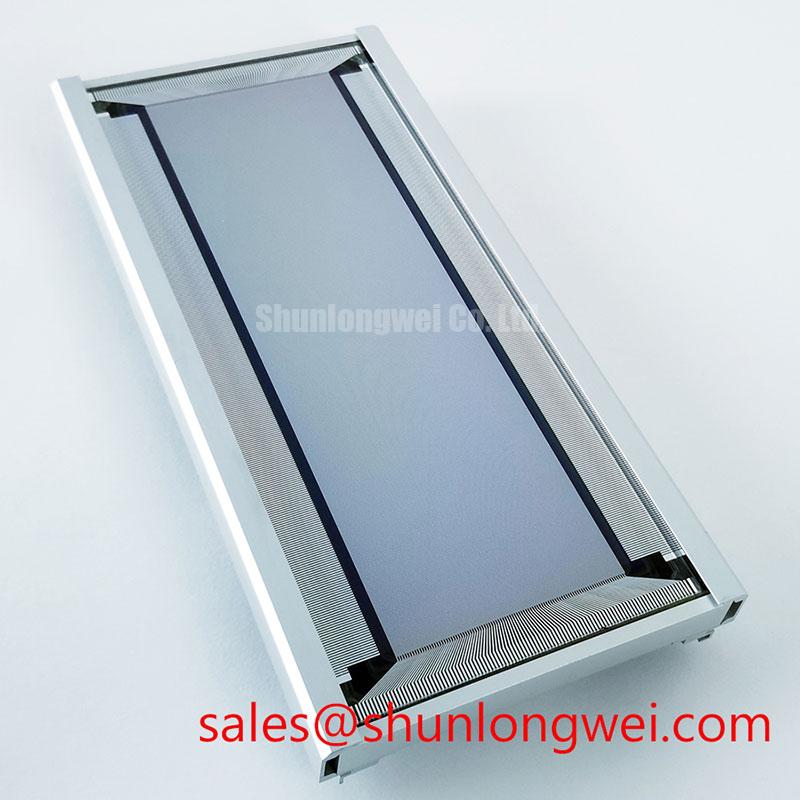
LJ640U21 is a Sharp industrial display component specified as an electroluminescent (EL) panel. Its EL construction is the confirmed technology designation; a numerical supply rating, connector pinout, dimensions, resolution, viewing angle and environmental rating are not established by the supplied factory specifications.
Display a known test pattern and inspect the LJ640U21 from the operator positions used by the equipment. Record any change in legibility across the viewing arc, then compare the result with the installed unit or the equipment acceptance criteria. Do not treat an unverified viewing-angle figure as a mounting requirement.
Because this part is specified as an EL panel, IPS and MVA liquid-crystal descriptions are not suitable evidence of its optical performance. The same distinction matters when assessing cold-start behaviour: an EL technology designation does not, by itself, establish a response-time or operating-temperature rating for this model. A proposed installation in a marine radar or navigation bridge console should therefore be evaluated against the console’s viewing positions, ambient conditions and original display documentation rather than an assumed wide-angle specification.
Keep the optical comparison separate from mechanical fit. LQ150X1LG11 is another display model that can be examined during a replacement assessment, but its dimensions, image format, electrical interface and mounting arrangement must be compared individually; the model names do not establish interchangeability.
Electroluminescent Drive Faults and Short-Circuit Screening
With the equipment isolated, inspect the LJ640U21 connector and accessible harness for contamination, damaged insulation and loose contacts before measuring the drive waveform at the interface specified by the host equipment. Compare the measured waveform with the original equipment service data. Do not apply a voltage inferred from general EL-panel practice: the supplied factory specifications do not establish a drive voltage or pin assignment for this model.
An EL panel depends on its associated drive circuit, so a dark or uneven image calls for separate checks of the panel connection and the upstream electronics. Observe startup and shutdown behaviour as well as steady operation; a supply that fails to settle, an interrupted connection or a driver fault may produce similar visible symptoms. If a short circuit is suspected, isolate the relevant circuit using the equipment schematic and compare its unpowered measurements with a known-good assembly where available. A resistance reading alone does not identify an internal dielectric defect.
Charge recovery, alternating drive and dielectric fault behaviour are useful design concepts, not confirmed circuit details of the LJ640U21. The separate LM057QC1T08 display model may be reviewed when documenting a broader display-system change, but it must not be treated as a driver or electrical companion to this panel without interface evidence. In cabinets supplied from three-phase mains, the three-phase power system is upstream of the display supply; its characteristics do not establish the waveform required at the panel connector.
Mounting Pressure, Seals and Local Image Defects
Inspect the gasket contact line and mounting points when a bright patch, dim region or intermittent image changes as the assembly is handled. Check whether the enclosure supports the display evenly without twisting its frame. Photograph the image before disturbing the mounting hardware, then compare it after the assembly has been reseated; a change is evidence to investigate, not proof of a single failure cause.
For a proposed bridge-console installation, designers should assess the enclosure seal and fastener arrangement against the equipment’s moisture and vibration requirements. The EL designation does not establish a hermetic rating or a shock rating for LJ640U21. Nor should an optical-bonding process be assumed: inspect the actual display assembly and its service documentation before specifying a bonded cover or replacement gasket.
Maintenance Note: Inspect the enclosure gasket and ventilation path during scheduled service, and isolate power before disconnecting the display harness.
Power Sequencing, Condensation and Return-to-Service Checks
Capture the panel-interface waveform through power-up and power-down when the image remains blank, appears late or persists unexpectedly after shutdown. Correlate the trace with the host controller’s enable signals and the original equipment schematic. This separates a sequencing problem from an image fault without assigning unsupported timing limits to LJ640U21.
Examine the enclosure for moisture tracks after temperature transitions, especially around cable entries and the display seal. Allow a damp assembly to reach a dry, stable condition under the equipment’s service procedure before repeating electrical tests. An enclosure assessment should account for condensation and salt exposure if a marine installation is being considered, but the panel’s own environmental tolerance cannot be inferred from that application.
Complete the return-to-service check with the intended image content at the installed viewing positions, followed by a shutdown observation. Record connector condition, measured drive behaviour, mounting condition and any remaining image irregularity. For distinctions between EL and liquid-crystal display terminology during a wider equipment review, consult The Ultimate Guide to Industrial TFT LCD Technology; its TFT LCD discussion should not be used as a specification for this EL panel.