

Content last revised on September 14, 2026
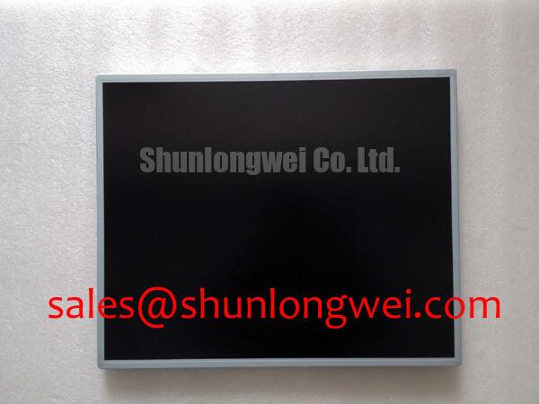
LB190E01-SL01 Industrial LCD/HMI Panel
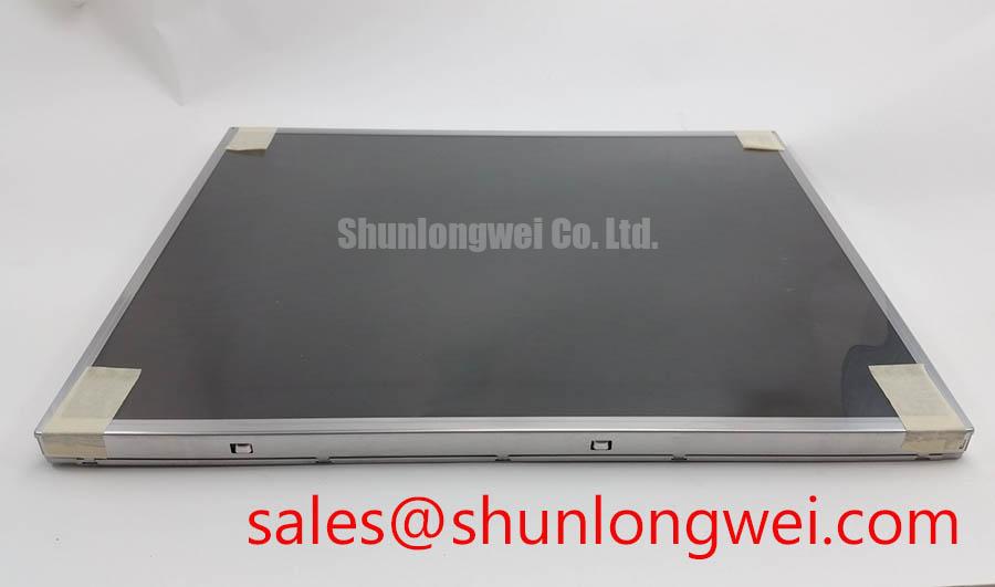
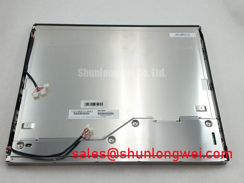
Inspect the replacement unit for glass-edge damage, connector condition, and visible bezel distortion before applying power, then confirm the label against LB190E01-SL01. The supplied factory record identifies this product as an Industrial Grade LCD/HMI Panel from LG Display, packaged as a TFT-LCD Display Module. Interface, resolution, dimensions, backlight electrical data, and mounting-hole details should be taken from the original panel documentation before installation.
| Model | LB190E01-SL01 |
| Manufacturer | LG Display |
| Product category | Industrial Grade LCD/HMI Panel |
| Package | TFT-LCD Display Module |
| Specification status | Factory Record Identified |
For sourcing and repair work, these verified identifiers establish the product category but do not by themselves confirm electrical interchangeability with another display. A CNC operator panel or robot teach pendant may require an exact match for display timing, connector orientation, logic supply, backlight control, and mechanical envelope. The system integrator should compare the removed panel’s documentation, cable assembly, controller output, and enclosure drawing before approving a replacement.
Constant Luminance Output Control and L70/B50 LED Half-Life Reliability Verification
Begin a luminance investigation by separating the display module from the host controller. A stable test image, uniform ambient conditions, and a known-good signal path help distinguish panel drive issues from backlight behavior. The available factory information for LB190E01-SL01 does not provide a verified L70, B50, LED half-life, MTBF, or constant-current operating limit. Those values must not be assigned to this model without the applicable LG Display document.
As a Design Consideration, inspect narrow display edges for localized heat transfer into the chassis. If the enclosure uses aluminum spreader rails, their contact pressure and electrical isolation should be checked against the panel construction and the original mechanical drawing. The objective is to avoid creating a local thermal or mechanical load that could affect image uniformity. Any L70 or B50 assessment should be based on the backlight supplier’s stated test method and the actual current, temperature, duty cycle, and airflow of the equipment.
For high-EMI factory equipment, differential routing should preserve pair symmetry and a continuous reference plane where the interface documentation requires differential signaling. Values such as characteristic impedance or skew limits are system-level design targets, not official specifications confirmed here. Designers should validate eye opening, clock quality, and conducted noise at the panel connector during the actual machine switching cycle.
Mechanical Stress and Glass-Substrate Driver-Bond Inspection
A practical bench check uses full-screen red, green, blue, white, and black images while observing the panel from normal viewing distance and at an oblique angle. A 45-degree flashlight inspection can reveal whether a dark region follows the illuminated area or remains associated with a fixed glass edge, cable region, or driver-bond area. This method is an observation aid rather than a proof of a specific internal failure mechanism.
When a line defect, intermittent region, or localized shadow changes as the panel is moved, avoid applying pressure to the glass or bonded edge. Record the fault with photographs, confirm the same pattern through a known-good controller, and check the cable seating without flexing the panel. The supplied specification context does not verify a particular COG construction, fracture threshold, or field failure rate for this model.
Backlight decay measurements should also remain evidence-based. A statement such as “50,000 hours to 50 percent brightness” cannot be attributed to LB190E01-SL01 unless it appears in the relevant manufacturer documentation. For service planning, engineers can log luminance, backlight current, operating temperature, and duty cycle over time, while treating any resulting trend as site-specific field data rather than a factory guarantee. Technical background on harsh-environment HMI integration is available in Industrial Display & HMI Solutions.
20-Pin or 30-Pin Differential LVDS Timing, Pixel Clock and Skew Compensation
Do not assume a 20-pin or 30-pin connector, LVDS mapping, TTL input, logic supply, or backlight control method from the model number. The original panel documentation should confirm connector pinout, supply voltage, enable sequence, pixel format, color depth, and JEIDA or VESA mapping. A replacement that powers up but uses a different mapping can produce split images, incorrect colors, unstable synchronization, or a blank screen.
During integration, verify the host board’s power-on behavior with an oscilloscope and compare the panel enable and video timing against the documented requirements. Differential pairs should be routed as a matched group with controlled return paths; the acceptable impedance and skew budget are determined by the transmitter, cable, receiver, and system compliance target. If the equipment combines a high-current backlight driver with the video interface, keep noisy current loops physically separated from the display clock and data routing.
The same validation applies when evaluating the neutral alternative NL192108JC18-03ND. Similar appearance or diagonal size is not sufficient evidence of compatibility. Compare active area, resolution, connector position, timing tables, mounting geometry, and backlight requirements line by line.
🔧 Bench Diagnostic: Disconnect power before reseating the display cable, and use the original connector keying and insertion direction during service.
Flush-Mount Open-Frame Bezel Integration and Perimeter Gasket Shock Isolation
Measure the host opening, panel seating surface, cable exit path, and fastener locations before machining or drilling. The official information supplied for LB190E01-SL01 does not include an outer bezel envelope, mounting-hole pattern, gasket specification, glass clearance, or approved fastener torque. These dimensions must therefore be verified from the original drawing or by controlled inspection of the removed unit.
As an Engineering Recommendation, use a compliant perimeter support that distributes enclosure contact without loading the active glass or bonded edges. Fasteners should be tightened in a cross pattern only after the panel is seated evenly, with the final torque determined by the chassis material, fastener size, gasket behavior, and LG Display mechanical guidance. Avoid using bezel pressure to correct an opening that is out of tolerance, since localized loading can present as mura, edge shading, or an intermittent display fault.
For a CNC operator panel or robot teach pendant, confirm that the display surface remains flush without cable strain when the enclosure is closed and when the assembly is exposed to normal vibration. A related display topology may be reviewed through LQ201U1LW31, but its electrical and mechanical data should be assessed independently rather than treated as interchangeable with this LG Display module. Where wave-soldered heavy leads or boundary-scan testing are relevant to the host board, consult Through-Hole Technology and Boundary Scan as general industry references.