

Content last revised on October 17, 2026
Electroluminescent Dielectric Pin-Hole Defect Self-Healing vs. Catastrophic Short-Circuit Screening
I check the disconnected Sharp LJ640U25 panel connector and its mating harness before investigating a dark screen, looking for displaced contacts, damaged insulation and contamination across adjacent conductors. The supplied EL construction description makes the display excitation circuit the relevant starting point. An LED backlight troubleshooting procedure would address a different display architecture and could send the repair in the wrong direction.
Field Alert: Isolate the equipment supply and verify that stored energy has discharged before disconnecting or reconnecting the display harness.
Design Consideration: Separate a missing image from missing panel excitation by checking the controller supply, enable signals and display data path against the equipment schematic. A blank display can accompany an interrupted harness, an inactive controller, a supply problem or a fault in the excitation stage. Record which signals remain present during the fault rather than assigning the symptom to the panel immediately. Compare observations with a functioning assembly of the same configuration where one is available.
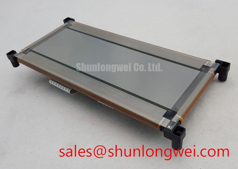
Design Consideration: In thin-film electroluminescent display technology, an alternating electric field excites the emitting structure through dielectric layers. A localized dielectric defect and a sustained short circuit require different interpretations. Localized clearing behavior depends on the actual construction and available fault energy; it is not a repair function that should be assumed for LJ640U25. Do not attempt to clear a suspected defect by increasing the excitation voltage or repeatedly restarting a protection cycle.
For waveform assessment, I would use a differential probe with suitable voltage and common-mode ratings, measuring across the intended excitation nodes. Design Consideration: Inspect alternating pulse balance, waveform shape and any persistent DC component against the original driver specification. Probe placement matters because a ground-referenced measurement can misrepresent a floating output or disturb its operation. Set the acceptance limits from the installed circuit and panel documentation; a generic EL drive amplitude is not a model-specific operating rating.
Design Consideration: Where the equipment schematic includes charge recovery, inspect the associated switching and energy-transfer paths before changing their tuning. Abnormal ringing, pulse collapse or increased supply demand can justify checking that stage, but each observation needs correlation with load condition and control timing. Recovery behavior depends on the display load and driver topology. Component changes should follow the equipment design and measured waveforms rather than an assumed resonant setting.
A useful fault record distinguishes connector damage, reproducible supply disturbance, missing control activity and abnormal excitation behavior. Design Consideration: Compare disconnected harness measurements with the schematic before interpreting resistance readings, since the meter can also see protection components and driver circuitry. A single resistance measurement does not establish dielectric integrity or identify the location of a fault. If the original service procedure permits load isolation, use that procedure to determine whether the abnormal behavior follows the panel assembly or remains with the driver.
Replacement assessment also requires a technology check. The Sharp LQ121K1LG61 can be considered as a separate display option during a broader equipment conversion review, subject to documented mechanical, electrical and controller compatibility. Its inclusion in a comparison does not establish interchangeability with LJ640U25. Match the mounting arrangement, active area, connector assignment, image timing and power architecture before treating any alternative as a practical service option.
Electro-Optical Response at Low Temperatures: Panel and System Qualification Checks
I separate image-update delay from emission behavior during a controlled temperature test by monitoring the controller output while displaying a repeatable changing pattern. This distinguishes delayed data delivery from a change at the display assembly. Design Consideration: Keep the test within documented equipment limits and allow the assembly to stabilize before comparing observations. Evaluate startup, steady operation and recovery separately because a satisfactory image after warmup does not establish reliable cold starting.
Design Consideration: Electroluminescent emission does not depend on liquid-crystal reorientation, but that physical distinction does not establish a response-time rating for this model. The observed update also includes controller processing, scan timing and the applied excitation waveform. Record those conditions with any optical measurement so that a response observation can be reproduced. Treat cold-temperature capability, shock resistance and viewing angle as separate qualification items, each requiring its own manufacturer specification or applicable test evidence.
For a dim or uneven image, compare a fixed pattern under controlled ambient illumination before adjusting the driver. Design Consideration: Check whether the change follows display position, operating temperature or the excitation waveform. An apparent loss of contrast can also involve the equipment window, reflections or contamination on an accessible surface. Inspect those surfaces using the equipment maintenance procedure; an antiglare or antireflection coating should not be attributed to LJ640U25 without a corresponding specification.
Power-path analysis must preserve the distinction between an emissive EL assembly and an LCD module with separate illumination. The Sharp LQ123K1LG03 is a separate display reference for evaluating another display architecture, rather than a verified auxiliary driver for this panel. Design Consideration: If an equipment redesign introduces another display technology, review its illumination supply, sequencing and fault reporting as a new subsystem. LED current regulation and backlight open-circuit protection should not be presented as established features of the LJ640U25.
When assessing a railway passenger information terminal or cab signalling display, designers should verify the complete installation against its equipment requirements. That review includes mounting support, connector retention, readable content under the intended lighting and operation across the specified environment. This is a compatibility assessment, not a statement of railway approval. Any touch interface belongs in the same system review: glove operation and wet-surface behavior depend on the installed touch sensor and controller, rather than the EL panel designation.
For broader comparison of display architectures and optical terminology, The Ultimate Guide to Industrial TFT LCD Technology provides related background. Manufacturer resources include the Sharp Display Solutions Official Portal and Sharp Devices Europe Industrial Display Solutions. Apply model-specific acceptance criteria when returning the assembly to service: confirm repeatable image updates, stable excitation, secure connections and satisfactory operation with the equipment enclosure fully assembled.