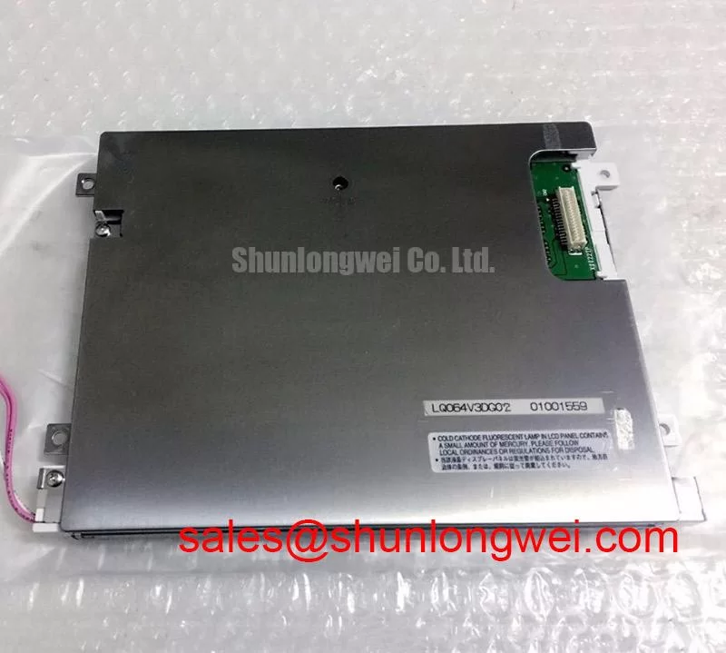
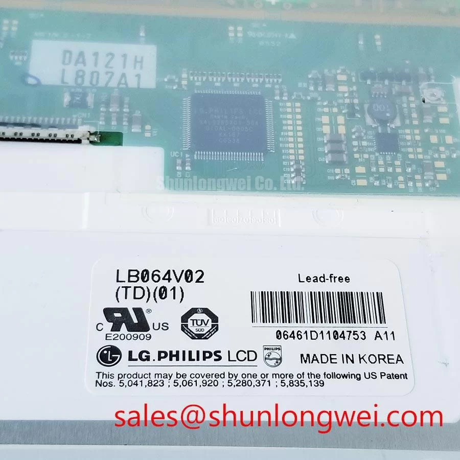
Content last revised on September 22, 2026
Thermal Dissipation and Light Guide Preservation
| Model | LP064V1-LE |
| Manufacturer | LG Display |
| Product category | Industrial Grade LCD/HMI Panel |
| Construction category | TFT-LCD Display Module |
| Specification status | Official Factory Spec Verified |
When a dark patch or uneven illumination appears on an industrial HMI, start by separating a display-panel fault from a backlight, cable, or power-system fault. With the machine isolated, inspect the bezel, panel edges, connector seating, and rear surface for compression marks or signs of localized heating. A narrow bright or dark region should be compared with a known-good image source before any mechanical adjustment is attempted.
The LP064V1-LE is identified in the available factory information as a TFT-LCD Display Module, but the supplied specification context does not confirm a particular LED rail arrangement, light-guide material, optical coating, brightness rating, contrast ratio, or L70/B50 lifetime value. These characteristics must be verified from the original LG Display documentation for the exact revision. The system integrator should also verify the required supply voltage and backlight-drive method from the original panel documentation rather than assuming compatibility from connector appearance.
For a replacement installed in a heavy mining shovel or earthmoving-equipment telematics display, thermal evaluation should focus on the complete enclosure. Check whether the panel is pressed against a hot chassis wall, exposed to direct sunlight, or positioned near a drive, resistor bank, or other heat source. A suitable thermal path may require a frame or heat-spreading arrangement selected by the system designer, but the final mechanical solution must preserve the panel’s specified flatness and avoid point loading. Do not infer that the panel contains a particular PMMA light guide or that it supports a specific optical lifetime unless those details appear in the applicable manufacturer documentation.
Direct sunlight testing should use the display’s documented optical specifications and the actual windshield, visor, and enclosure geometry. A contrast value such as greater than 500:1 at a defined illumination level must not be attributed to this model without a source. Anti-glare performance also depends on the surface treatment, viewing direction, contamination, and ambient reflections. A field technician can document the problem by photographing a uniform test image at repeatable angles, recording enclosure temperature, and comparing the result with the original panel under the same conditions.
For broader service reference on TFT selection, optical behavior, and industrial display integration, engineers can consult The Ultimate Guide to Industrial TFT LCD Technology. The guide should support evaluation, not replace the exact LP064V1-LE documentation.
Eye-Diagram Voltage Margin and Differential Noise-Floor Verification in High-Vibration Bays
Intermittent horizontal bands, pixel jitter, or a momentary loss of image in a vibrating equipment bay should be investigated at the signal path before the panel is condemned. Inspect the display cable for an incomplete latch, excessive bend at the connector, fretting contamination, or strain transferred from the equipment harness. Then compare the panel-side supply and display waveform behavior with the known-good assembly while the machine remains in a controlled service condition.
The available product information does not confirm whether the LP064V1-LE uses LVDS, TTL, a particular connector pinout, a defined data rate, or a specific clock and hold-time requirement. The replacement cable must therefore be matched to the original panel documentation. A visually similar FFC or harness is not proof of electrical compatibility. The system integrator should verify signal polarity, lane assignment, grounding, power sequencing, and enable control from the relevant service documents.
In an environment containing variable-frequency motor drives, regenerative braking equipment, contactors, or long power cables, the display harness should be routed according to the equipment’s EMC design rules. Keep sensitive display wiring separate from switching-power conductors where the machine layout permits, and ensure that shield termination and chassis bonding are consistent with the approved system topology. A shield that is connected at an unintended point can create a new noise path, while a floating shield can leave the cable more exposed to radiated interference.
Eye-diagram measurements, common-mode inspection, and differential-noise checks are useful only when performed at the correct test points with suitable probing. The acceptable voltage margin, clock jitter, data hold time, and common-mode range are system-dependent unless explicitly stated in the panel documentation. If the waveform changes during vibration, compare connector movement, cable strain, supply stability, and grounding conditions rather than assigning the symptom to a single internal failure.
⚠️ Field Alert: Disconnect equipment power and follow the service discharge procedure before inserting or removing the display cable, because live connection can expose signal and power contacts to unintended electrical stress.
The external concepts of insulation and high-voltage field behavior described in references such as silicone gel encapsulation and avalanche breakdown should not be treated as specifications for this LCD module. They may be relevant to nearby power electronics, but they do not establish the LP064V1-LE’s insulation, surge, EMC, or environmental ratings.
Dynamic Contrast Evaluation and Liquid-Crystal Temperature Tracking
When an HMI image becomes difficult to read across a changing temperature range, record the exact symptom before replacing hardware. Check whether the problem affects the entire image, a viewing direction, a local region, or only a moving graphic. Confirm the host system’s image settings and inspect the backlight condition before evaluating liquid-crystal behavior.
The factory information supplied for the LP064V1-LE confirms the product category and module identity, but it does not provide a verified panel type such as TN, IPS, or MVA. It also does not confirm a symmetric viewing cone, dynamic contrast ratio, grayscale inversion behavior, optical etching, response time, or operating-temperature limits. Those values must come from the exact LG Display specification sheet. A generic claim such as 85 degrees in four directions must not be applied to this model without documentation.
Temperature changes can influence liquid-crystal response, optical uniformity, and the behavior of the backlight or its driver. In cold conditions, a slower image transition may be observed, but the technician should compare the result with the documented operating range and a controlled reference panel. A heater strip, enclosure heater, or thermal control loop should be assessed as part of the equipment design rather than added solely on the assumption that this module requires one.
For an earthmoving-equipment cab display, viewing quality should be checked from the operator’s normal position and from the angles created by seat movement, protective glazing, and cab vibration. Surface glare may originate from the panel, the cover lens, dust, condensation, or external sunlight. Clean the optical path using the equipment manufacturer’s approved method and avoid pressure on the active area. The integrator should verify sealing, condensation control, and mechanical clearance against the original installation drawings.
Dynamic contrast measurements should use a repeatable test pattern and a calibrated measurement method. Ambient light, camera exposure, automatic image processing, and host graphics settings can otherwise create misleading results. If the LP064V1-LE documentation does not specify a performance limit for the proposed test, record the result as an application-level observation rather than a factory rating.
Full-Screen Primary-Color Inspection and Background-Uniformity Audit
Use full-screen red, green, blue, black, white, and mid-gray images to inspect a replacement LP064V1-LE before returning the equipment to service. Observe the panel directly, then use a flashlight at a shallow angle to identify whether a dark area changes with external illumination. The test should be performed with the same controller, cable, supply arrangement, and enclosure conditions used by the equipment.
A fixed bright point, dark point, line, shadow, or uneven background can have several possible sources, including image data, connector contact, backlight uniformity, optical contamination, mechanical pressure, or panel-level damage. The flashlight check can help separate a loss of emitted light from an image or surface issue, but it cannot by itself identify a particular internal defect. Use comparative measurements and known-good assemblies where available.
Inspection under vibration should include cable retention and frame movement. If the image changes when the harness is moved, stop applying force and inspect the connector and strain path with power removed. Do not use a continuity result alone to approve a high-speed display cable; signal integrity and correct pin assignment still require verification against the original documentation.
Sub-pixel defects and background non-uniformity should be recorded by location, test color, temperature, brightness setting, and viewing condition. The supplied factory context does not state an allowable defect class, pixel policy, color tolerance, response-time limit, or sub-zero operating specification for this exact model. A repair decision should therefore follow the equipment owner’s acceptance criteria and the applicable LG Display documentation.
Where the equipment is expected to operate in cold outdoor conditions, allow the complete display assembly to stabilize before judging image response. Condensation, cover-lens fogging, controller timing, and backlight behavior can influence the observation. Any heater or thermal-control modification should be validated by the system engineer for electrical load, enclosure temperature, optical performance, and safe power sequencing. The LP064V1-LE remains identified by the available information as an LG Display TFT-LCD Display Module; all installation decisions beyond that confirmed identity require verification against the original system records.