

Content last revised on September 10, 2026
Full-Screen Primary Color Inspection: Stuck Sub-Pixels & Background Uniformity Audit
| Model | LB064V02-TD01 |
|---|---|
| Manufacturer | LG Display |
| Product Category | TFT-LCD Display Module |
| Display Construction | TFT-LCD Active Matrix Color Display Module |
| Specification Status | Detailed specifications require verification from the applicable documentation |
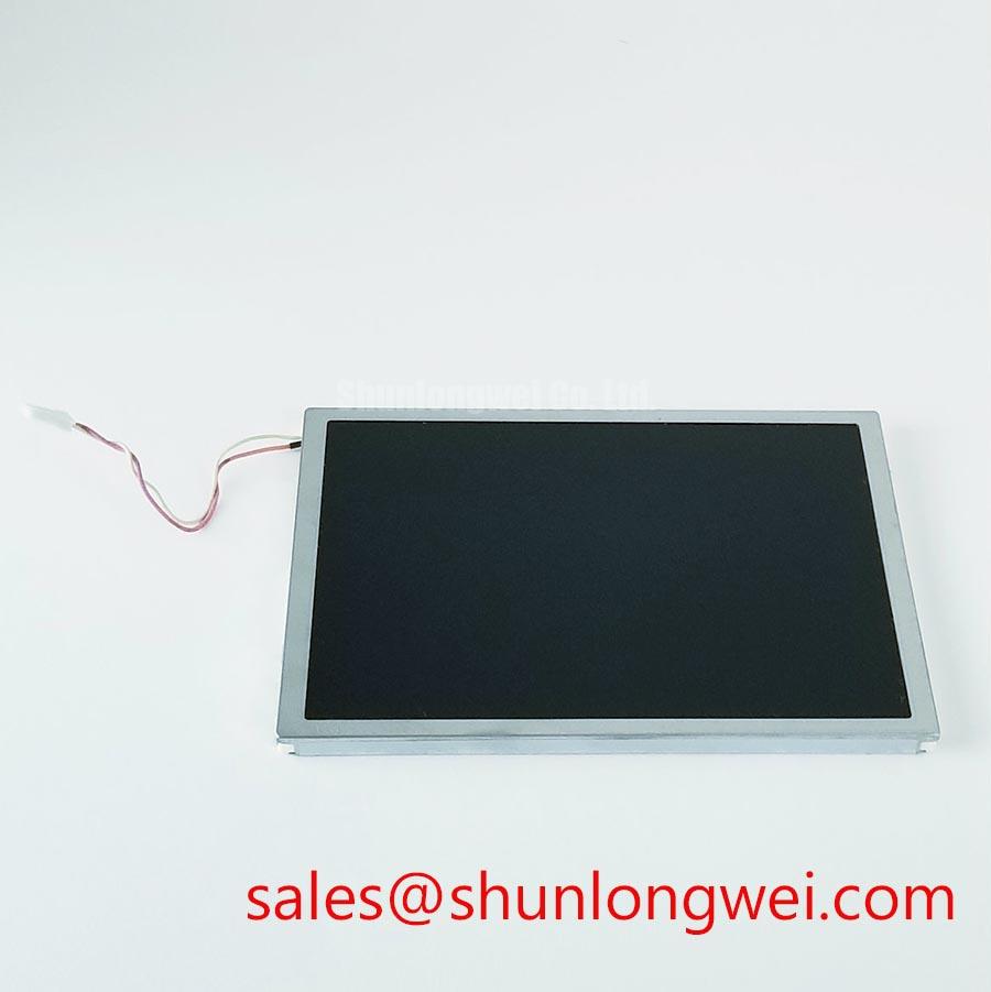
Drive the replacement display through full-screen black, white, red, green, and blue test images while observing the active area from normal viewing distance and at close range. A pixel that remains illuminated or dark through all color fields should be logged separately from a broad brightness variation, because the two visual conditions point to different inspection paths. Record the location relative to the bezel and connector side so that later observations remain repeatable after reassembly.
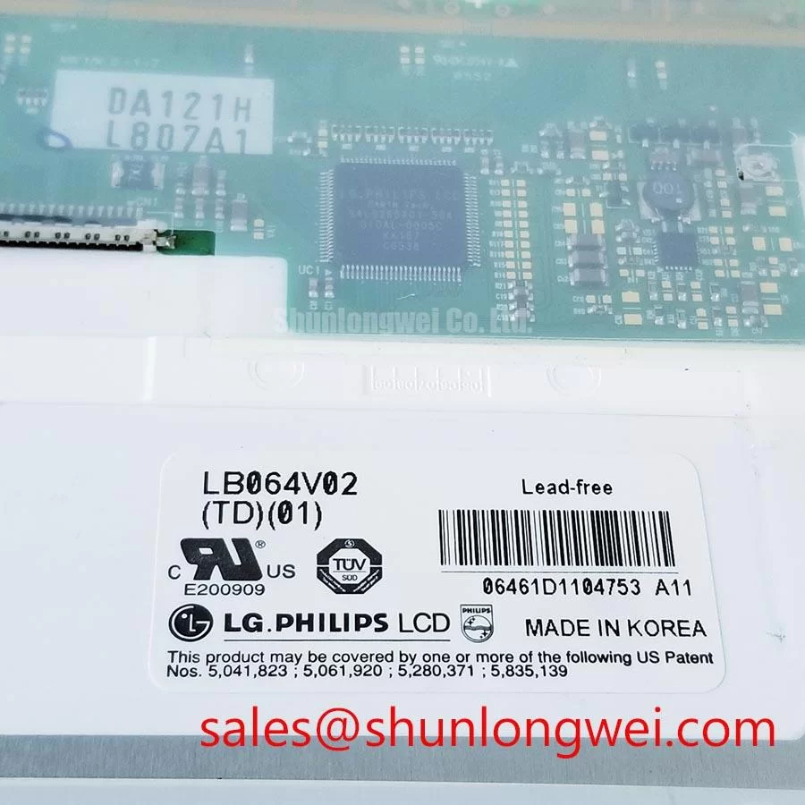
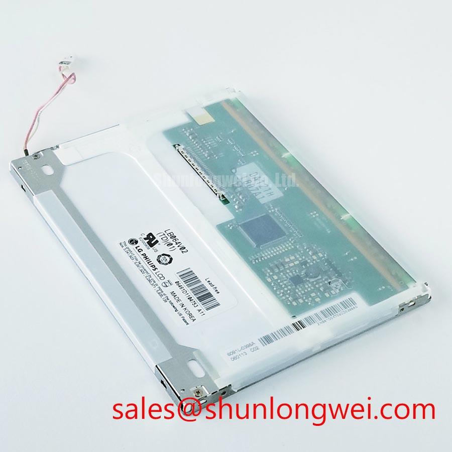
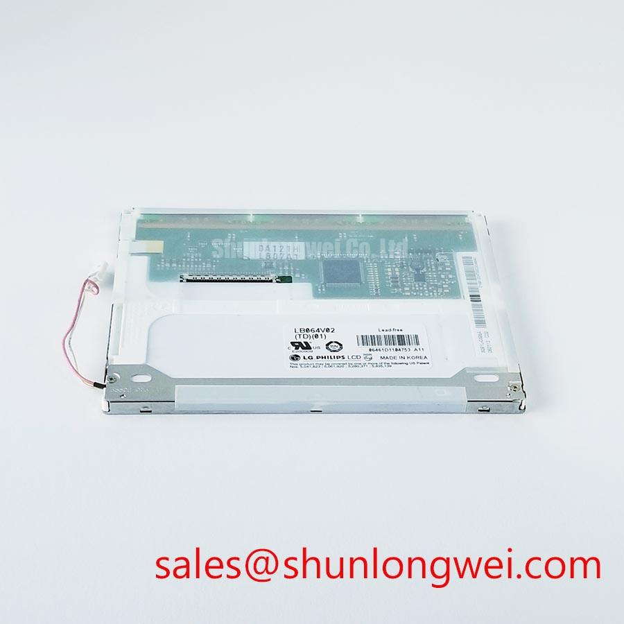
For LB064V02-TD01, the confirmed product identity is an LG Display TFT-LCD Active Matrix Color Display Module. The available official product information does not establish pixel resolution, interface type, backlight technology, operating voltage, luminance, viewing angle, or touch configuration. The system integrator should verify the required supply voltage, signal interface, timing format, and mating connector from the original equipment panel documentation before applying a substitute panel to a controller board.
Use a controlled visual sequence rather than relying on the running application screen. A white field is useful for revealing local clouding, edge pressure, or contamination under the front window. A black field can reveal residual light leakage and uneven illumination. Red, green, and blue fields make isolated sub-pixel behavior easier to distinguish from a source-image problem. If a line, intermittent band, or color shift follows the displayed test pattern, inspect the controller output and cable path before attributing the symptom to the panel assembly.
At a shallow viewing angle, a hand-held inspection light can help reveal whether a dark region is associated with the optical stack, front contamination, enclosure shadowing, or a display-drive artifact. Keep the light outside the active image path and compare observations with the unit installed in its original bezel. A line that changes with cable movement, vibration, or temperature stabilization may indicate a connection or signal-integrity issue. Verify the waveform against a known-good signal path where that comparison is available.
If the host board uses a TTL or LVDS display connection, signal-clock stability, data setup timing, and hold timing remain system-level requirements rather than panel-specific values unless confirmed by the original documentation. Design Consideration: inspect the transmitter, harness, grounding path, and connector retention across the actual temperature range of the equipment. Temperature-related intermittent artifacts can originate at the host transmitter, cable termination, connector contact, or the panel interface, so a single visual symptom should not be treated as a single confirmed cause.
🔧 Bench Diagnostic: Disconnect and reconnect display cables only with system power removed and stored energy discharged to avoid stressing the panel interface.
Front Surface and Optical Uniformity Inspection under Direct Industrial Lighting
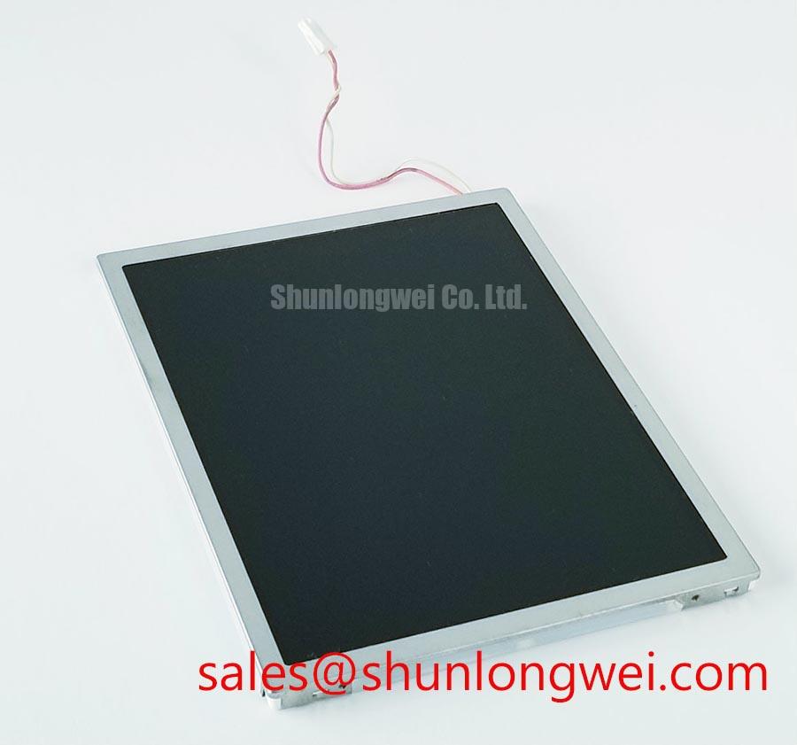
Inspect the powered panel under the same direct lighting angle that produces the field complaint, then compare the image while changing the display content from dark grayscale to mid-gray and white. This method separates reflections from panel-originated contrast changes and makes surface marks, haze, pressure patterns, and uneven bezel loading easier to identify. Clean only with materials approved for the equipment’s display window and avoid pressing the active area during inspection.
The LB064V02-TD01 factory identification confirms a TFT-LCD module, but it does not confirm the liquid-crystal mode, polarizer finish, anti-glare treatment, anti-reflective treatment, viewing cone, or response-time specification. It should not be described as TN, IPS, MVA, anti-glare, or high-brightness without the applicable manufacturer documentation. These optical properties materially affect integration decisions in bright work areas and outdoor-facing enclosures.
Design Consideration: direct industrial lighting can make reflections appear as loss of contrast, especially when a protective window, gasket, or front overlay introduces a second reflective surface. Examine the panel with the enclosure door open and then with the intended window and gasket fitted. If the appearance changes significantly after the bezel is tightened, inspect whether mounting force is distributed evenly around the display perimeter. Uneven compression can create local visual distortion or light non-uniformity without proving an internal panel defect.
Cold conditions may alter perceived LCD response and grayscale behavior. Where equipment is exposed to low ambient temperatures, maintenance personnel should compare startup behavior after thermal stabilization with behavior observed at normal indoor conditions. Any external heater strip, condensation-control device, or enclosure heater is a system-level feature and must be evaluated against the original equipment design, power budget, thermal controls, and safety documentation.
Moisture protection deserves equal attention. Inspect the display window seal, perimeter gasket, drain path, cable entry, and enclosure breathing arrangement for signs of trapped moisture or hardened sealing material. Condensation can interfere with optical inspection and can also affect adjacent electronics. When evaluating a panel for a navigation bridge console or similarly exposed industrial terminal, verify enclosure sealing and environmental qualification at the equipment level rather than assigning those attributes to the display module alone.
For broader troubleshooting methods covering optical symptoms, interface checks, and industrial TFT integration, consult The Ultimate Guide to Industrial TFT-LCD Technology.
Backlight Supply and Driver Inspection
Trace the backlight supply from the host power board to the display connector and confirm the original panel documentation before measuring or energizing any lamp or driver circuit. The official information for LB064V02-TD01 does not identify its backlight type, inverter arrangement, LED driver arrangement, dimming method, ignition requirement, current rating, or expected brightness retention. Do not assume a CCFL backlight, an LED backlight, PWM dimming, or a specific high-voltage characteristic for this model.
A dark display can arise from several places in the assembly: missing panel logic power, absent image data, disabled backlight control, a cable fault, host-driver protection activity, or an optical problem that is only visible under external illumination. Observe whether the panel image is present with a controlled external light source, then inspect the host controller’s enable behavior and supply rails using the original service information. This avoids replacing a display module when the actual fault remains upstream in the equipment.
Engineering Recommendation: when a host system contains a separate backlight driver, evaluate the driver and its protective response as a complete circuit with its approved load conditions. An inverter or constant-current driver can respond to abnormal cable conditions or load characteristics by shutting down, cycling, or reporting a fault. Those behaviors should be compared with the original schematic, service procedure, and known-good equipment rather than interpreted from a single voltage observation.
Acoustic noise, flicker, intermittent dimming, or delayed illumination should be observed during cold start, steady operation, and after enclosure vibration or cable movement. These symptoms may indicate a driver, cable, connector, power-supply, or control-path issue. Inspect connector seating and strain relief without twisting the display connector or applying force to the panel edge. Where an external window and gasket are fitted, confirm that the backlight area is not being mechanically loaded by the enclosure hardware.
Maintenance Note: regularly inspect cooling air paths, display-window seals, and cushioning gaskets because blocked airflow and degraded sealing can complicate backlight and condensation diagnostics.
Display Signal Integrity and Noise Verification in High-Vibration Bays
Probe the display signal at the host output and at the panel-side connector while the equipment reproduces a stable test pattern and nearby loads are switched. A horizontal noise band, random pixel shimmer, intermittent image loss, or display recovery after cable movement may indicate disturbance in the signal path, connector retention, shield termination, grounding arrangement, or host electronics. Compare the captured waveform with a known-good installation whenever practical.
The official specification set for LB064V02-TD01 does not confirm LVDS, TTL, cable shielding requirements, differential impedance, pair skew, or connector pinout. Interface assumptions can damage a panel or host board. The system integrator should verify the exact interface assignment, power sequencing, connector orientation, and signal timing from the original panel documentation and the equipment schematic before constructing or modifying a harness.
Design Consideration: keep display signal routing physically separated from high-energy switching conductors where enclosure geometry allows, particularly around motor drives, contactors, braking circuits, and power conversion equipment. The purpose is to reduce coupled electrical noise that can affect low-level display data or control lines. The final routing, shield connection method, ferrite selection, grounding topology, and acceptable waveform margin must be determined through system-level testing in the actual equipment.
Inspect the cable path for repeated flexing near hinges, sharp bends, loose clamps, unsupported connector weight, and rubbing against metalwork. High-vibration locations can create intermittent contact behavior that is difficult to reproduce on a bench. Secure the harness using the equipment’s approved retention method, then repeat the full-screen color test while monitoring for image disturbance. If the symptom disappears only after cable repositioning, inspect the complete path rather than treating the panel as the only suspect.
For display assemblies installed behind a front window, verify that the shield or cable braid does not become trapped beneath a gasket or compressed against the panel edge during closure. Mechanical strain and electrical noise control must be addressed together: a stable image requires both reliable physical retention and a verified host-to-panel signal path.