

Content last revised on November 14, 2026
LTM09C362A Display Identification and Replacement Checks
- Disconnect equipment power and compare the panel label, connector orientation, and cable routing with the removed display before attaching the replacement.
- Inspect the mounting supports and bezel clearance for uneven contact, trapped cables, or pressure against the display face.
- Check the controller schematic for RGB signal assignments, pixel clock polarity, and the required panel power sequence.
- Record whether the original fault affects illumination, image data, grayscale uniformity, or startup behavior before changing hardware.
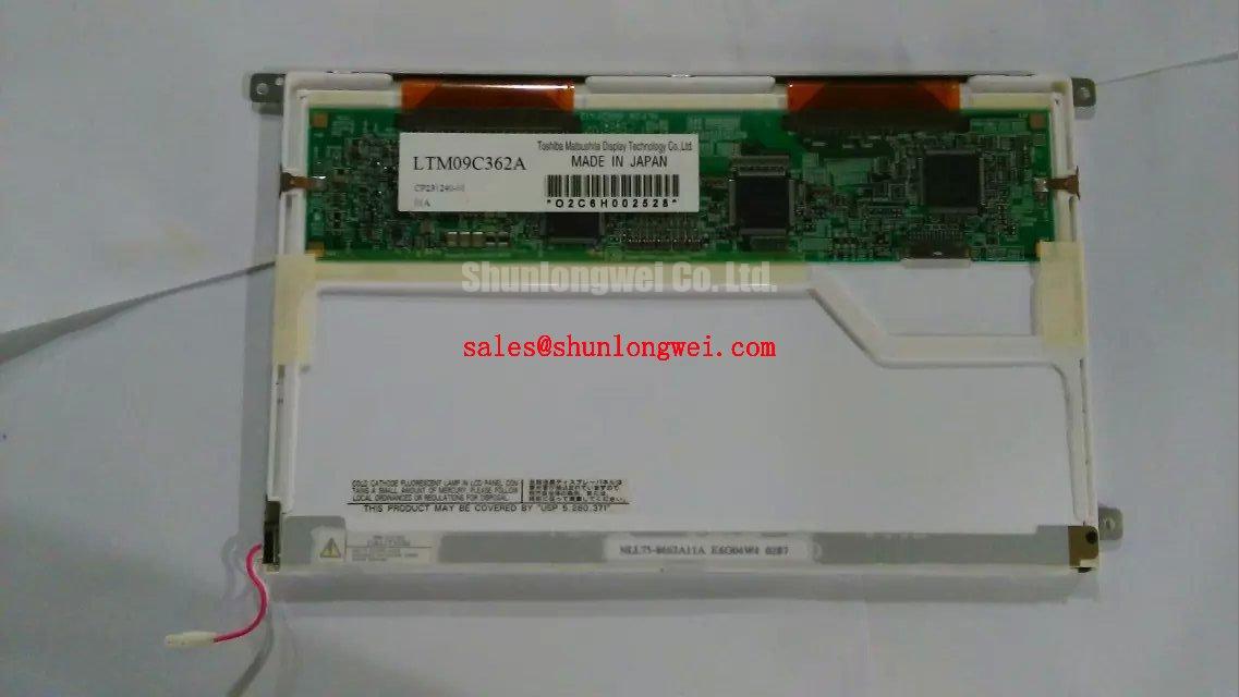
The LTM09C362A is a TFT-LCD Active Matrix Color Display Module with a Diagonal Size: 8.9 inch, Resolution: 640 x 480, and Interface: RGB. Its supplied product information identifies Part Number: LTM09C362A, with a luminance baseline of 200 cd/m². These characteristics establish the initial display and controller comparison; they do not establish connector interchangeability.
Consult the datasheet for supply voltage, connector pinout, signal timing, backlight architecture, optical treatment, outline dimensions, mounting requirements, and environmental limits. The supplied manufacturer designation, “Toshiba / Samsung,” is ambiguous and should be reconciled with the equipment bill of materials and panel label during procurement.
For an industrial automation CNC operator panel or robot teach pendant, compatibility evaluation should cover the complete display assembly, including the controller, illumination driver, front window, and mounting arrangement. Matching the resolution alone does not establish a suitable replacement.
Evaluating Anti-Glare (AG) and Anti-Reflective (AR) Treatments for High Ambient Readability
Compare a grayscale test image under the intended ambient lighting and operator viewing position before attributing poor readability to the panel electronics. Reflections, viewing-angle contrast changes, and unstable pixel data produce different symptoms and need separate checks. The 200 cd/m² luminance baseline describes emitted brightness, not readability through a reflective protective window.
Design Consideration: anti-glare treatment scatters reflected light, while anti-reflective treatment reduces reflection through its optical design; these terms are not interchangeable. Neither treatment is established for this model by the baseline specifications. Evaluate the assembled front window and display together, because a reflective cover can dominate the result even when the underlying image remains stable.
Design Consideration: TN grayscale inversion changes apparent tone ordering with viewing direction, whereas IPS and MVA technologies generally offer broader viewing characteristics. These are technology-level comparisons, not an identification of the LTM09C362A cell mode. Inspect dark gradients, mid-gray fields, and fine text from actual operator positions rather than assigning a symmetric viewing cone to this panel.
The specified RGB interface also requires a disciplined signal check. Engineering Recommendation: compare data transitions with the receiving clock edge at the panel connector, using the documented setup and hold requirements. Temperature-dependent changes in controller delay, cable loading, and receiver behavior can reduce timing margin. A stable test pattern at room conditions does not establish operation across the equipment’s required temperature range.
RGB does not establish an LVDS interface. Where a host includes an LVDS bridge, JEIDA or VESA mapping belongs to that bridge’s configuration and must be reconciled with its RGB output assignments. Pro Tip: Preserve the documented clock-to-data timing relationship through the cable and any interface bridge, and validate it at the panel connector rather than only at the controller output.
CCFL High-Voltage Inverter and Ignition Debugging Considerations
Identify the installed backlight driver and its output connections before applying any ignition test. Dual-channel CCFL operation is an equipment-side architecture to investigate, not a confirmed LTM09C362A specification. Use the driver’s service procedure and suitable measurement equipment when examining a high-voltage illumination circuit.
Design Consideration: CCFL ignition and sustained lamp operation are different electrical conditions. A backlight that flashes briefly before shutting down can involve the driver supply, lamp connections, protection circuitry, or the illumination assembly. Compare startup behavior with the equipment’s documented sequence rather than treating a brief flash as proof of a single failed component. Acoustic noise likewise needs correlation with the driver waveform and mechanical mounting.
Constant-current LED drivers use a different operating principle and cannot be treated as interchangeable with a lamp inverter. During an assembly-level conversion assessment, the driver, illumination load, enable logic, dimming control, thermal arrangement, and mechanical fit all require compatibility checks. No LED conversion or backlight type is implied by the panel’s RGB image interface.
Engineering Recommendation: separate illumination troubleshooting from image-path troubleshooting. Check whether the controller produces a stable image while observing driver enable and supply behavior during startup. Coordinate panel power, valid RGB data, and illumination enable according to the equipment timing requirements. White-screen startup or residual images after shutdown can involve sequencing or supply decay and should not automatically be classified as backlight faults.
Backlight maintenance decisions should distinguish brightness depreciation from failure statistics. A time-to-reduced-brightness claim is not an MTBF rating, and neither follows from the panel’s luminance specification. For this assembly, assess brightness consistency after thermal stabilization and compare driver behavior with the service reference. Engineering Recommendation: evaluate dimming through its usable control range for flicker, audible noise, and image interference, with operating settings determined by the installed driver and system validation.
Preventing Mechanical Stress and Investigating Dark-Field Uniformity Defects
Display a uniform dark-gray field while checking whether bright patches or shading change when the bezel is released. A repeatable relationship with enclosure pressure supports a mechanical-loading investigation, although it does not identify a particular internal optical layer as the cause. Avoid diagnosing light guide plate deformation solely from the appearance of a dark-field defect.
Design Consideration: the module should seat on its intended supports without the front window, gasket, or cable forcing it out of plane. Compare bracket alignment, support height, opening clearance, and cable exit space before tightening the enclosure. Use the assembly’s documented fastening method and torque specification rather than applying a generic screw-size rule to the display.
Thermal expansion can alter those clearances after warm-up. Engineering Recommendation: inspect uniformity after the equipment reaches a representative operating condition, with the enclosure assembled as intended. Compare the location of shading with nearby heat sources and mounting contacts. Uneven brightness can involve illumination distribution, temperature, electrical drive, or mechanical stress; changing one condition at a time makes the observation more useful.
Optical bonding also changes the mechanical and optical assembly. A bonded cover requires a qualified material and process assessment for adhesion, cure behavior, optical appearance, and thermal movement. Bonding should not be assumed to provide a moisture barrier or correct an existing pressure defect. Ambient-light contrast must be assessed through the finished front assembly rather than inferred from nominal luminance.
When comparing the LTM084P363 as another sourcing reference, evaluate its documented outline, active-area position, mounting arrangement, and electrical interface independently. A related model designation or comparable display class does not establish drop-in compatibility. Procurement drawings should distinguish the visible image opening from the module envelope so that a replacement is not rejected or accepted on diagonal size alone.
High-Humidity Storage and Delamination Prevention
Define storage and qualification conditions from the applicable panel and equipment requirements before exposing the assembly to heat or moisture. Do not assume that a high-humidity test condition is an approved storage rating for the LTM09C362A.
Design Consideration: bringing a cold display into warmer humid air can create condensation on accessible surfaces and connections. Allow the assembly to reach suitable handling conditions before energizing it, and inspect for moisture, edge lifting, clouding, or connector contamination. Record changes under consistent illumination so that surface condensation is not confused with a persistent optical defect.
Lower temperature generally increases liquid-crystal response time, but the resulting behavior depends on the cell and drive conditions. The reference on Liquid-Crystal Display Response Time (Gray-to-Gray) explains why response measurements depend on the transition being measured. For equipment validation, examine moving text and changing grayscale patterns at approved operating conditions rather than extrapolating a room-temperature observation into a response-time guarantee.
Engineering Recommendation: assess image persistence separately from illumination flicker. Observe whether the effect follows changing image content, a backlight dimming command, or the shutdown sequence. Camera recordings can introduce their own flicker artifacts, so correlate them with direct observation and electrical measurements. Dimming frequency and duty behavior should follow the installed driver’s capabilities and the equipment’s acceptance criteria.
The Marine LCDs Technical Reference provides broader environmental integration context without establishing a marine qualification for this panel. For the actual enclosure, review gasket condition, cable-entry sealing, and moisture paths around the front assembly. After storage or servicing, recheck edge appearance, grayscale uniformity, connector condition, and startup behavior before returning the equipment to operation.