

Content last revised on October 16, 2026
Industrial LCD HMI Panel Replacement and Integration
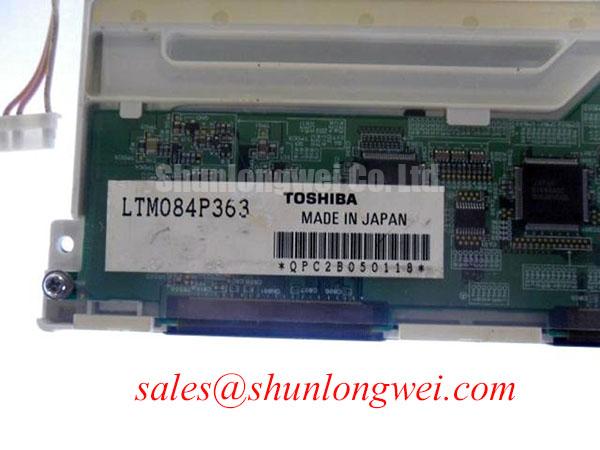
When an AGV or forklift telematics display goes dark, isolate the panel from the machine before replacing parts: inspect the display cable seating, check the backlight supply path, and compare the active image signal with a known good unit. The LTM084P363 is identified as a Toshiba / Samsung TFT LCD active matrix color display module for industrial HMI integration.
This product category does not provide enough evidence to assign a universal supply voltage, interface pinout, backlight type, optical bonding construction, or viewing-angle specification. The system integrator should verify those values from the original panel documentation and the equipment service drawing before applying power. For repair purchasing, match the mechanical outline, connector position, signal protocol, backlight driver arrangement, and mounting method rather than relying on model-family similarity alone.
In a direct replacement assessment, engineers can compare the LQ084S3DG01 as another display option, while keeping electrical and mechanical compatibility checks separate from the part number comparison. The LTM084P363 is also relevant to industrial HMI panels where the original display module must be restored without changing the host controller or enclosure design.
Backlight Driving, PWM Dimming and Flicker Control
Backlight troubleshooting should begin at the driver output and proceed toward the panel connector. A dark image with visible graphics can indicate a backlight path problem, while a completely absent image requires separate checks of the panel supply, timing controller activity, and host video signal. Do not treat a replacement LED driver as part of the LTM084P363 specification unless the original assembly documentation identifies it that way.
Legacy equipment may use high voltage CCFL ignition, with cold-start values sometimes specified by the original inverter documentation around the 1500 to 1650 Vrms range. That range must not be transferred to this model without confirmation. A constant-current WLED driver is a different electrical topology, and its compliance voltage, current regulation, enable logic, and dimming input are determined by the selected driver and panel assembly.
For a system using PWM brightness control, a proposed 200 Hz to 1 kHz operating range is a Design Consideration, not an official LTM084P363 rating. The commissioning engineer should observe the backlight waveform, confirm that brightness follows the control command smoothly, and check for audible behavior or visible modulation at the actual installation point. A 1000:1 dimming ratio and a half-life or MTBF figure must likewise come from the relevant backlight or driver datasheet, not from the display model designation.
When the panel is used in an AGV or forklift display, examine cable strain and connector retention while the vehicle is stationary and during controlled vibration checks. Uneven illumination can also be associated with driver current imbalance, optical assembly damage, or local thermal concentration. The correct repair path is to compare current behavior and luminance distribution with the original service baseline before changing the panel.
Radiated Emissions Control and Backplate Grounding
Pixel jitter and horizontal noise bands near a variable frequency motor drive should be investigated as a complete signal-path problem. Route the display cable away from switching power wiring where the enclosure permits, maintain the intended shield termination, and inspect every bond between the cable shield, panel support, and chassis reference.
A 360 degree shield termination and common-mode ferrite are system-level interference-control methods, not confirmed construction features of the LTM084P363. Their suitability depends on the cable assembly, connector geometry, chassis bonding, and the frequency spectrum produced by the motor inverter. Engineers should verify emissions at the installed system level because a display module cannot independently claim CISPR Class A or Class B compliance for the completed machine.
Cold environments add a separate timing concern. Liquid-crystal response can become slower as temperature falls, which may appear as extended gray-to-gray transitions or motion smearing rather than a digital signal fault. If a heater or enclosure temperature-control circuit is used, its control behavior should be validated against the panel manufacturer’s permitted operating conditions. Do not add a heater strip as a presumed accessory of this model.
For the backlight supply, keep the current return path distinct from sensitive video references where the system topology requires it. The related LQ10D213 may be evaluated as a separate auxiliary or front-end display solution, but its electrical role must be confirmed independently during the equipment redesign.
⚠️ Field Alert: Remove power before disconnecting or reconnecting the display cable, and allow the supply rails to discharge according to the equipment service procedure.
Grayscale Behavior and Viewing Direction
Viewing direction should be checked from the operator’s actual seated or standing position, not only from a straight-on bench inspection. TN, IPS, and MVA technologies can produce different grayscale transitions, contrast behavior, and color shifts as the viewing angle changes. The available product identity confirms an active matrix color display module, but it does not establish a specific panel technology or a symmetric 85° viewing cone.
For forklift and AGV terminals, compare dark gray, mid-gray, and warning-color screens while the display is mounted at its final angle. A perceived grayscale inversion or color change may result from viewing direction, ambient reflections, controller gamma settings, or the panel technology itself. The optical response described in the original panel documentation should control any decision about firmware gamma correction or mechanical tilt.
Signal integrity remains important in high-EMI cabinets. A 100 ohm differential impedance target with a 10 percent tolerance and a 50 ps skew budget can be used only when it matches the actual interface standard and host design; these are Design Considerations, not LTM084P363 factory specifications. The engineer should inspect pair routing, reference continuity, connector seating, and termination behavior, then verify the signal eye or waveform against a known-good path. Changing the panel without checking the host timing can leave the original fault unchanged.
Surface glare should be evaluated with the enclosure lighting, sunlight, and operator protective equipment in place. Anti-glare treatment, optical bonding, and cover-window construction must be confirmed from the complete display assembly documentation. The technical background of LCD polarizers and optical glass helps explain why reflected light and polarization direction can alter the perceived image, but it does not define the construction of this specific module.
Frame Lag and Image Smearing in Cold Industrial Facilities
At sub-zero temperatures, image motion should be tested with a moving diagnostic pattern rather than a static screen. Increased liquid-crystal viscosity can lengthen gray-to-gray transitions, making fast icons, map movement, or camera imagery appear soft even when the digital frame stream is intact. This is a general LCD behavior and should not be presented as a confirmed operating rating for the LTM084P363.
Thermal cycling also places demands on the enclosure, bezel, cable bend area, and any sealant used by the finished equipment builder. A range such as minus 30°C to plus 85°C is a system test condition only when supported by the component and enclosure specifications. Engineers should establish the permitted storage and operating limits from the original documentation, then check startup, image stability, contrast, and recovery after temperature exposure.
Power sequencing deserves attention when the display shows a white screen at startup, residual imagery after shutdown, or intermittent recovery. Confirm the host controller’s reset behavior, panel supply rise and fall, backlight enable timing, and video initialization order as one sequence. The correct delay and threshold values are system-determined; they should be validated with the installed controller and driver rather than copied from another LCD family.
Long-term static HMI screens should use the host system’s approved screen-management strategy, such as controlled page rotation or reduced static brightness where appropriate. Do not assume that optical bonding, an anti-glare surface, or a particular backlight architecture is included in this module without assembly-level evidence. For broader background on panel selection, interface planning, and industrial TFT integration, consult The Ultimate Guide to Industrial TFT LCD Technology.