

Content last revised on October 18, 2026
LMG6911RPBC-00T Panel Identification and Replacement Checks
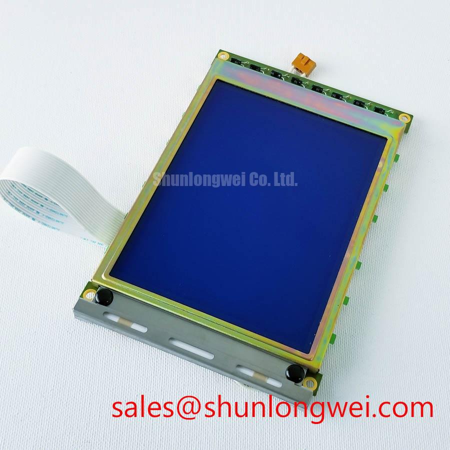
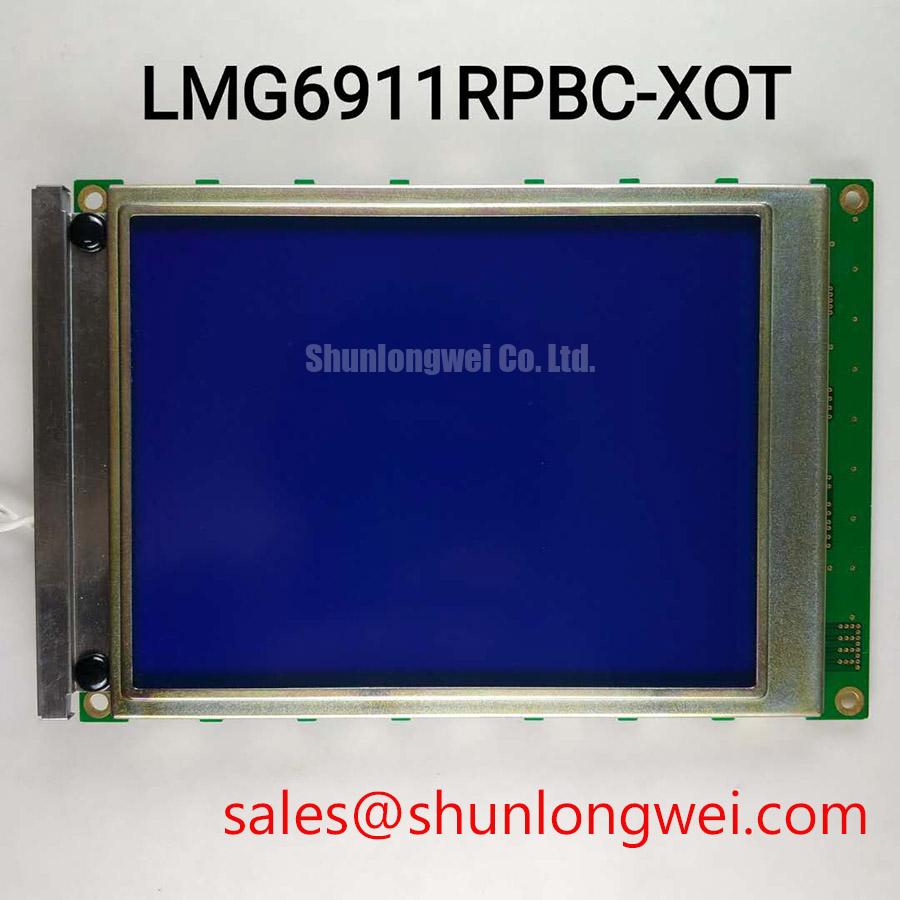
- Check the replacement panel against the marked LMG6911RPBC-00T reference and confirm the original connector and mounting pattern.
- Inspect the display opening, gasket contact area, and cabinet airflow path for dust, compression damage, or uneven support.
- Confirm the host controller’s display interface, logic supply sequence, contrast bias circuit, and backlight architecture before energizing the panel.
- For AGV and forklift installations, review vibration transfer, condensation exposure, daylight readability, and cable locking before final assembly.
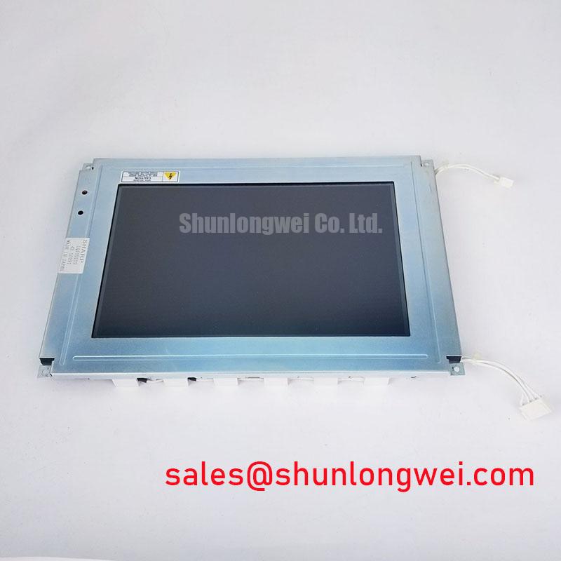
The LMG6911RPBC-00T is identified as a KOE / Hitachi monochrome passive matrix LCD panel. It should be evaluated as a display panel within the original HMI assembly rather than as a complete controller, backlight driver, or finished vehicle terminal. The host system must provide the supply rails, interface timing, contrast bias arrangement, and illumination method required by the panel documentation.
| Parameter | Product information |
|---|---|
| Model | LMG6911RPBC-00T |
| Manufacturer | KOE / Hitachi |
| Display category | LCD panel for HMI integration |
| Panel type | Monochrome passive matrix LCD panel |
On Board Charge Pump vs. External DC DC Negative Bias Supply Ripple Suppression
Contrast stability depends heavily on the quality of the liquid crystal bias rail, especially when the panel is installed in an older HMI with a separate negative voltage generator. The often discussed Vee or V0 range of minus 15 V to minus 24 V should be treated as a system integration reference, not as a confirmed product rating for this panel. The original display documentation and the host board schematic should establish the correct value.
During service, observe the bias rail under cold start, normal display activity, and backlight operation. Excessive ripple can become visible as contrast modulation or unstable grey levels, but the acceptable limit is determined by the panel circuit and controller. Compare the rail directly at the display connector rather than only at the DC DC converter output, since cable resistance, return routing, and charge pump loading can alter the result.
A thermistor compensation network may be present in the original equipment to account for temperature dependent liquid crystal response. At low temperature, viscosity related response changes can make text transitions appear slower even when the digital data is correct. At high temperature, contrast can fade if the bias relationship drifts. When restoring an original circuit, retain the sensing location and thermal coupling arrangement. Do not add a compensation curve based only on a generic STN panel assumption.
For a replacement evaluation, compare the panel at the same viewing angle and ambient illumination used by the vehicle terminal. Reflective and transflective viewing conditions can make a contrast fault appear to be a backlight fault. A service engineer can also compare the bias waveform with a known good terminal while checking whether the charge pump is being overloaded by leakage, contamination, or an incorrect capacitor.
Logic Power 5.0 V or 3.3 V Versus Liquid Crystal Bias Power Up Sequence Coordination
The host controller should establish digital logic power before applying the liquid crystal bias rail, following the sequence specified by the original panel documentation. The presence of a 5.0 V or 3.3 V logic system cannot be assumed from the model name. Applying the wrong logic level or allowing the bias rail to rise while the controller pins are undefined can place unwanted DC stress across the liquid crystal drive system.
Parallel monochrome interfaces commonly use frame synchronization, line pulses, and a dot clock. Where the documented interface uses FLM, LP, and CP, inspect these signals together with the data lines. A stable image requires correct relationship between frame timing, line transfer, and pixel data; a panel with correct illumination can still show shifted characters, missing rows, or unstable contrast when the timing relationship is wrong. Use the original controller configuration as the reference instead of changing clock polarity and pulse width at random.
Clock edge quality is also affected by cable length, ground return inductance, connector oxidation, and poorly controlled routing near the backlight converter. An oscilloscope comparison at the panel connector can separate a timing fault from a bias fault. Designers should keep the digital return path controlled and avoid routing sensitive display signals alongside high voltage backlight wiring.
When integrating this panel into an AGV or forklift telematics display, the enclosure interface deserves the same attention as the electrical interface. Uneven bezel pressure can distort the visible area and create localized optical nonuniformity. The gasket should contact evenly around the display opening, while the mounting structure should allow vibration loads to be distributed rather than concentrated at one corner.
CCFL Ballast Capacitor Selection and Tube Operating Current Stabilization
If the original terminal uses a CCFL backlight, the ballast and lamp circuit must be assessed as a matched system. Confirm the ignition voltage, sustained operating voltage, and lamp current from the original backlight documentation. The correct lamp type, ballast network, insulation spacing, and current target belong to the original backlight assembly.
Cold starting is particularly sensitive to lamp condition, ballast capacitor selection, transformer behavior, and ambient temperature. A lamp that strikes intermittently can produce visible flicker, uneven illumination, or repeated converter protection. Measure the current with an instrument and method suitable for the high voltage circuit, then inspect the ballast waveform for abnormal ringing or failed regulation. Never connect a replacement lamp or capacitor solely because its physical dimensions appear compatible.
For modernized equipment, the replacement architecture may use a separate LED backlight driver. In that case, the system integrator should verify the required current regulation, dimming interface, thermal path, and connector pinout from the replacement backlight and driver documentation. If PWM dimming is used, a system designer may evaluate a control range around 200 Hz to 1 kHz for visible flicker behavior, but that range is a design consideration rather than a specification of the LMG6911RPBC-00T.
Backlight reliability should be judged from measured temperature, current stability, and enclosure conditions. A quoted 50,000 hour figure, when encountered in a backlight specification, belongs to the complete light source and operating conditions, not automatically to the LCD panel. The external LM64C15P page can be reviewed as a related display solution when mapping the surrounding backlight and panel topology.
Transflective or Reflective Polarizer Aging and UV Degradation
Legacy monochrome displays used in bright vehicle cabins should be checked for optical aging before adjusting the electronics. Yellowing, cloudy adhesive regions, edge bubbling, reduced daylight contrast, and a slow change in viewing angle response can originate in the polarizer or bonding layers rather than in the controller. The exact internal optical construction of this model should not be inferred from the FSTN or STN designation alone.
Use a controlled comparison under the same ambient light level and viewing direction. A reflective or transflective panel can appear weak when a service bench light is positioned differently from the original instrument cluster. General polarization principles are discussed in the reference on circular polarizers. This optical reference does not define the construction of the LMG6911RPBC-00T.
UV exposure, cleaning chemicals, heat, and trapped moisture may accelerate visible aging in older terminals. “Vinegar syndrome” refers to degradation of cellulose acetate materials that releases acetic acid; it should not be declared as the failure mechanism without physical evidence. Look for odor, edge lifting, haze, adhesive bubbles, or progressive contrast loss across the active area, then compare the panel with the equipment’s service history.
⚠️ Maintenance Note: Inspect the cabinet airflow path and display gasket during scheduled service, and replace damaged sealing material before dust or condensation reaches the panel edge.
For a broader interface comparison, engineers can review LM32K071 when assessing another industrial display option with the required size, resolution, connector arrangement, and optical behavior. The Industrial TFT LCD Technology reference may also support wider maintenance planning, while the final replacement decision remains dependent on the original HMI’s mechanical, electrical, and optical interface.