

Content last revised on October 12, 2026
Thermal Expansion Clearance Sizing across Heavy Industrial Metal Enclosure Cutouts
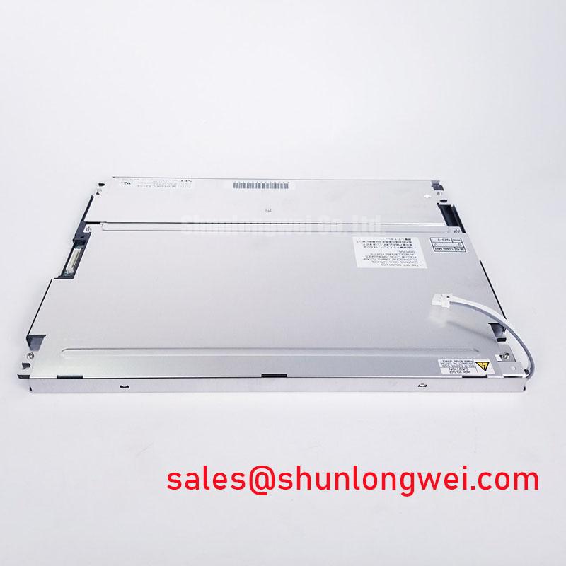
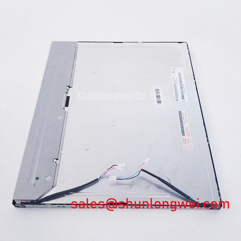
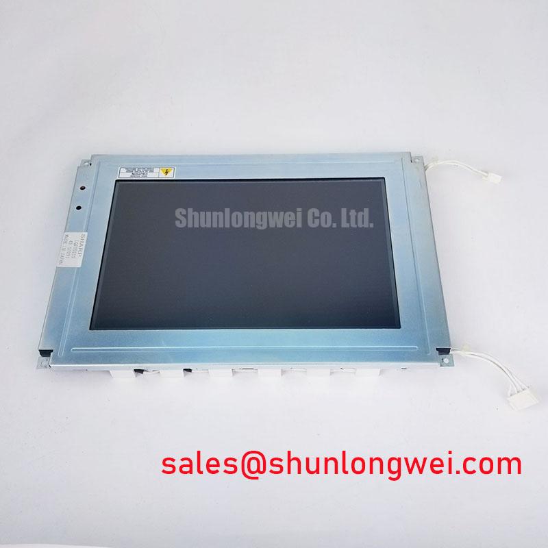
Check the metal cutout, bezel contact points, and diagonal mounting pattern before applying power to a replacement Sharp LQ10D213. The supplied product baseline identifies this part as a TFT LCD active matrix color display module in a standard form factor; enclosure compatibility still depends on the original equipment drawing, panel opening, connector position, and fastening arrangement.
Place the display into the enclosure without tightening the fasteners, then inspect whether the bezel rests evenly around the opening. A rigid metal panel can transfer local stress into the display assembly when the enclosure expands or contracts. Uneven contact may appear as a dark corner, localized brightness variation, or an optical mura pattern that changes when the mounting screws are loosened. These symptoms should be assessed mechanically before replacing the display electronics.
Use a cross-pattern tightening sequence and follow the equipment manufacturer’s fastening specification. The supplied baseline does not define an LQ10D213 mounting torque limit, so a generic torque value must not be treated as an official Sharp parameter. Designers should allow the chassis, bezel, gasket, and panel to move within their intended mechanical tolerances rather than forcing the module into an undersized cutout.
For equipment exposed to sub-zero conditions, compare the displayed image during cold start and after the enclosure reaches its normal operating temperature. Liquid crystal response can become visibly slower at low ambient temperature, while a heater or controlled enclosure may alter the thermal gradient across the viewing area. Any heater strip, temperature controller, or insulation method remains system dependent and should be validated against the original equipment design.
⚠️ Field Alert: Disconnect power before loosening the panel or removing the display cable, then support the module evenly to avoid twisting the glass assembly.
Single Vertical Hairline Defect & Sub-Pixel Column Driver Open-Circuit Localization
When a single vertical line appears, switch the display through full red, green, blue, white, and black test fields while observing whether the line remains fixed at the same column. A line that persists across primary colors deserves a different inspection path from a broad dark region or an image that disappears when the backlight level changes.
Use a controlled bench signal and record the defect at each color field. The three-color comparison helps separate image data abnormalities from illumination problems, but it does not by itself prove a column driver open circuit. Compare the suspect panel with a known-good signal path, inspect the cable seating, and verify that the defect is not moving with the source or timing controller.
A flashlight held at approximately forty five degrees can help reveal whether image information is present beneath a dark appearance. If faint image content is visible while the backlight appears inactive, investigate the illumination and driver path. If the line remains sharply defined with normal illumination, focus the inspection on the panel interface, flexible cable contact, and column addressing path.
Do not press the glass edge or bonded driver region to make a line disappear. A pressure-induced change can provide a useful observation during controlled service evaluation, but it can also create additional damage. The LQ10D213 baseline supplied for this page does not specify a backlight technology, brightness rating, or rated lifetime, so LED lifetime curves and half-brightness claims should not be assigned to this model without the relevant Sharp documentation.
For compatible system planning, the LQ121S1DG31 can be reviewed as a separate display option. Its mechanical dimensions, optical properties, interface, and electrical requirements must be compared independently rather than assumed from the LQ10D213 designation.
Radiated Emissions Compliance via Backplate Multi-Point Star Grounding
Pixel jitter and horizontal noise bands near variable frequency motor equipment should be traced through the complete display signal path, not attributed to the LCD module alone. Start at the host controller, follow the display cable routing, and inspect whether the cable runs alongside switching power conductors or motor output wiring.
A shielded FFC or LVDS cable can reduce unwanted coupling when its shield termination, chassis bonding, and connector arrangement match the system design. Grounding points should provide a low impedance path for high frequency common-mode current while avoiding accidental return paths through sensitive signal references. The correct arrangement depends on the enclosure, cable construction, host board, and grounding architecture.
Where a differential display interface is used, designers should verify the pair routing, termination, spacing, and skew against the interface documentation and the host controller requirements. A commonly used differential target such as 100 ohms with a defined tolerance is a system design consideration, not an official LQ10D213 specification. Oscilloscope checks at the receiving end are more useful than judging cable quality by appearance alone.
Ferrite components may be evaluated when conducted or radiated interference is identified, but their impedance profile must match the frequency range and current conditions of the actual circuit. Adding a component without checking its effect on signal integrity can exchange a noise problem for an intermittent display fault.
Sharp’s Industrial Display Solutions and Display Solutions Official Portal provide useful manufacturer-level context for industrial display integration. The complete equipment remains responsible for EMC evaluation; a display module alone should not be presented as independently certified to CISPR limits.
Suppressing Acoustic Capacitor Buzz & EMI Emissions across PWM Frequencies
Separate audible noise, visible flicker, and brightness instability before changing the dimming circuit. Listen to the power assembly during brightness transitions, observe the image with a high-speed camera or oscilloscope where appropriate, and compare the result with the backlight enable and dimming signals defined by the host equipment.
The LQ10D213 baseline confirms the product category and display construction but does not confirm CCFL, LED, PWM range, dimming depth, ignition voltage, constant-current architecture, or backlight lifetime. Those values must therefore be taken from the original panel and inverter documentation before a replacement driver is selected. A CCFL inverter and an LED constant-current driver are not interchangeable simply because the display opening is the same.
For a system using PWM dimming, a frequency within the equipment’s intended control range should be selected after checking camera sensitivity, operator comfort, acoustic behavior, and driver switching losses. The frequently used 200 Hz to 1 kHz range is a design consideration rather than a Sharp LQ10D213 rating. Check duty-cycle linearity at low brightness, because an apparently stable command can still produce uneven illumination if the driver loses regulation near its lower operating boundary.
When the display is integrated into a surgical navigation or ultrasound diagnostic terminal, verify the host supply, backlight control, image timing, connector orientation, and enclosure bonding against the original system documentation. The LQ150X1LG71 may be reviewed as a separate Sharp display solution in related system planning, while its interface and backlight requirements must be assessed independently.
For structured troubleshooting of display grounding, enclosure integration, and HMI service practices, consult the Industrial Display & HMI Solutions reference alongside the equipment service manual.