

Content last revised on September 24, 2026
Suppressing Acoustic Capacitor Buzz and EMI Emissions in PWM-Controlled Display Systems
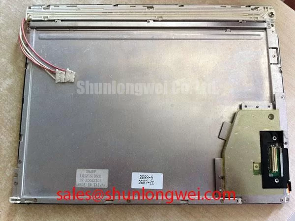
With the host controller de-energized, measure the logic supply at the panel power pins, inspect the mating connector for incomplete engagement, and check the display perimeter for mechanical stress before powering an LQ121S1DG31 replacement assembly. A dark image, a uniformly white raster, intermittent sparkle, or a screen that recovers after cable movement should be investigated at the power and signal path before the panel itself is blamed.
The Sharp LQ121S1DG31 LCD display has a stated logic-supply requirement of 3.3 V or 5.0 V ± 0.5 V, identified as an Official Datasheet Specification in the supplied product data. The equipment integrator should verify which rail is required from the original panel documentation and the host-board connector assignment. A valid supply measurement alone does not prove correct sequencing, signal mapping, or backlight operation, but it establishes the first electrical boundary for repair work.
| Parameter | Specified Value | Classification | Verification Focus |
|---|---|---|---|
| Logic supply voltage | 3.3 V or 5.0 V ± 0.5 V | Official Datasheet Specification | Measure at the logic power pins with a digital multimeter. |
| Differential line impedance | 100 Ω ± 10% | Design Consideration | Evaluate differential routing with appropriate TDR or signal-integrity methods. |
| Chassis screw torque | 0.35–0.45 N·m | Design Consideration for M3 fasteners | Confirm with a calibrated digital torque screwdriver. |
| Backlight lifetime | More than 50,000 hours typical | Official Datasheet Specification | Assess luminance against the stated threshold of more than 50% of initial brightness. |
When an industrial terminal presents a visible image but emits an audible tone during brightness adjustment, separate the panel investigation from the external illumination and power circuitry. The supplied data for LQ121S1DG31 defines backlight lifetime performance but does not identify the fitted backlight technology, inverter topology, cold-start voltage, dimming method, PWM frequency, contrast ratio, anti-glare treatment, or sunlight-readability rating. Those attributes must therefore be confirmed from the original equipment documentation rather than assumed from the display model alone.
Acoustic noise often deserves examination because it can be mistaken for a panel fault when the actual source is an associated driver board, a power inductor, a ceramic capacitor, or a mechanically excited enclosure surface. With the display connected in its original system, technicians can compare the audible behavior during a controlled brightness change, observe whether the image remains stable, and inspect whether vibration or cable position changes the symptom. If the sound changes while the image remains electrically stable, the result may point toward the supporting power assembly rather than the LCD cell.
EMI evaluation should also remain at the system level. The panel cannot be presented as independently compliant with equipment-level EMC requirements. As a Design Consideration, controlled differential routing helps reduce susceptibility to noise introduced by adjacent switching loads, motor drives, and vehicle power electronics. The supplied 100 Ω ± 10% differential impedance target is useful when reviewing an interconnect or replacement controller layout, but a cable, connector, common-mode environment, grounding arrangement, and transmitter configuration can all affect the final result.
For AGV and forklift telematics displays, engineers should verify visual readability with the actual enclosure, front cover, and mounting angle under the site lighting conditions. Direct ambient light, dust on a protective window, and reflections from warehouse lighting can reduce perceived contrast even where the panel is functioning normally. The practical test is to compare a known-good screen and the repaired unit using the same host terminal, content pattern, enclosure window, and illumination conditions.
Where a maintenance team is comparing display options during a repair assessment, the LMS700KF01-001 can be reviewed as a separate product reference. Its mechanical, electrical, optical, and interface characteristics must be checked independently against the failed equipment before any compatibility decision is made.
Backlight Thermal Management and Optical Preservation
A dim image should first be distinguished from a missing image. In a controlled service setting, inspect the panel with a suitable test pattern, confirm whether image content is present, and then examine the associated illumination path and driver supply. The supplied factory information confirms a typical backlight lifetime of more than 50,000 hours, measured with optical luminance assessment at more than 50% of the initial brightness. This is an Official Datasheet Specification, not a guarantee of field operating duration in every enclosure or duty cycle.
The available specifications do not state that the LQ121S1DG31 uses edge-lit LEDs, a PMMA light guide plate, a high-nits backlight, or an L70/B50 lifetime classification. These terms should not be assigned to this model without original manufacturer documentation. If a vehicle terminal shows progressive dimming, uneven illumination, color change, or flicker, technicians should inspect the panel connection, power path, driver board, enclosure temperature, and observed luminance rather than attributing the condition to one internal material or mechanism.
Thermal control remains a Design Consideration for the completed equipment. Heat from nearby power stages or a sealed telematics enclosure can affect the display assembly and its supporting electronics. The appropriate heat-spreading arrangement, ventilation method, duty cycle, and brightness strategy are system-determined and should be validated with measurements in the finished device. Avoid placing unsupported conductive or compressive materials against the display edges, because an external modification can create optical non-uniformity or interfere with the intended mechanical fit.
Signal integrity is relevant in electrically noisy factory and vehicle environments. The supplied 100 Ω ± 10% differential impedance value is a Design Consideration for trace verification. Differential-pair skew should be managed according to the host interface requirements and validated against the known-good signal path, particularly where the cable route passes near switching converters or traction-related electronics. Sparkle noise, pixel jitter, or intermittent horizontal disturbances may indicate a signal-path issue, although connector wear, poor grounding, transmitter behavior, or cable damage should also be checked.
For broader enclosure, display-interface, and environmental evaluation practices, maintenance teams can consult Industrial Display & HMI Solutions. That reference is useful for planning a structured test sequence, while the LQ121S1DG31 replacement decision should remain tied to the original terminal’s documented electrical and mechanical requirements.
Industrial Bezel Mechanical Envelope Tolerances and Mounting Screw Torque
Before transferring a display into a field terminal, compare the panel outline, mounting locations, connector orientation, bezel opening, and cable clearance with the removed unit. No physical dimensions, bezel tolerances, viewing-angle technology, optical bonding construction, or front-surface treatment are included in the supplied product data for the LQ121S1DG31. These items must be verified against the original panel, equipment drawings, and approved service documentation before installation.
The stated chassis fastening range is 0.35–0.45 N·m as a Design Consideration for M3 screws. This range is not presented as an unqualified manufacturer mounting instruction for every terminal enclosure. It provides a controlled starting reference when the original equipment uses compatible M3 fasteners and the mechanical stack-up has been verified. The actual fastener length, thread engagement, bezel material, gasket arrangement, and mounting bracket stiffness remain system-dependent.
Installers should tighten compatible fasteners gradually in a cross-pattern while observing the panel face for localized pressure effects. Excessive or uneven loading can contribute to visible pressure marks, cell-gap distortion, perimeter mura, or an apparent dark region that is mechanical rather than electronic. Do not infer that a recurring optical defect is automatically caused by screw torque; enclosure deformation, foreign material, bracket misalignment, or a damaged protective window can produce similar observations.
Field Alert: Disconnect power and allow the host system to discharge before removing or inserting the display cable, because live connector handling can disturb signal-pin levels.
Where a telematics terminal includes a bonded cover lens or environmental seal, retain the original assembly method unless the equipment documentation authorizes a different procedure. The supplied data does not establish optical bonding, moisture sealing, dust ingress performance, vibration qualification, or vehicle certification for this panel. For an AGV or forklift display, the completed terminal assembly should be evaluated by its integrator for its installed environment rather than treating the LCD as a self-certified rugged subsystem.
Digital RGB Bus Synchronization and Logic Power Rail Verification
Start logic-side diagnosis by confirming the exact host interface and power-pin assignment from the original panel documentation. Although this section addresses digital RGB synchronization, the supplied specifications do not confirm a TTL interface, 24-bit color bus, JEIDA mapping, VESA mapping, pinout, connector type, data format, or timing definition for the LQ121S1DG31. A replacement should never be connected solely on the basis of connector appearance or a presumed digital-interface convention.
The official logic supply requirement is 3.3 V or 5.0 V ± 0.5 V. The system integrator should verify the required supply voltage from the original panel documentation before energizing the unit. A white screen, logic failure, or abnormal driver behavior can occur when the logic rail is outside the documented requirement, but those symptoms can also arise from incorrect signal mapping, a defective host board, connector contamination, interrupted return paths, or an unstable supply under load.
The supplied data does not define power-on rise time, power-down timing, permissible signal-before-power conditions, or reset sequencing. For this reason, the correct procedure is to capture the host power and signal behavior from a known-good installation where possible, then compare the replacement assembly under the same conditions. Designers should ensure that the host system follows the panel manufacturer’s documented sequencing requirements and verify the observed behavior during switching tests rather than applying generic timing values.
For differential signal paths, 100 Ω ± 10% is identified as a Design Consideration. When split images, unstable pixels, horizontal sparkle, or intermittent recovery occur, inspect cable seating, shield continuity where applicable, connector retention, host transmitter output, and route exposure to electrical noise. Compare signals with a known-good path using suitable test equipment. This approach avoids treating a visible fault as proof of a single cause and keeps the repair decision tied to measurable conditions at the LQ121S1DG31 interface.