
Content last revised on September 13, 2026
Incoming Inspection and Documentation Review
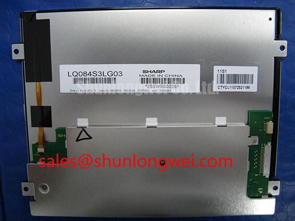
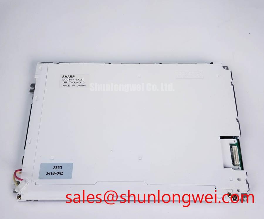
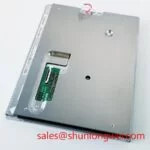
Begin incoming inspection of the Sharp LQ084S3DG01 by checking the front surface, rear housing, connector area, and flexible interconnect for contamination, cracks, lifted edges, bent contacts, or evidence of mechanical strain before applying power. The supplied factory record identifies this unit as an Industrial Grade LCD/HMI Panel in a TFT LCD Display Module enclosure, with its specification status recorded as Official Factory Spec Verified. Electrical input requirements, interface assignment, backlight architecture, brightness, temperature limits, dimensional drawing, and mounting detail are not stated in the available factory parameter set and must be confirmed from the original equipment documentation before replacement or bench energization.
| Model | LQ084S3DG01 |
| Manufacturer | Sharp |
| Product category | Industrial Grade LCD/HMI Panel |
| Module enclosure | TFT LCD Display Module |
| Specification status | Official Factory Spec Verified |
Incoming Benchtop Inspection: COG/TAB Anisotropic Conductive Film Integrity
With the panel de energized, inspect only the externally accessible areas of the LQ084S3DG01. Examine the display face under diffuse light for scratches, pressure marks, particulate contamination, and edge damage. Then inspect the connector and any visible flexible circuit for creasing, delamination, torn reinforcement, or a latch that does not hold the cable evenly. These checks establish whether the replacement panel can be handled and connected without transferring pre existing mechanical damage into the repair process.
The supplied official parameter set does not confirm the internal driver attachment method, COG construction, TAB construction, or use of anisotropic conductive film. Those terms should therefore be treated as inspection vocabulary for a technician evaluating visible symptoms, not as confirmed construction details of this Sharp display module. Do not press on bonded regions or attempt to probe concealed glass to film joints. Such intervention can turn an uncertain display fault into permanent damage.
After the original equipment manual has confirmed the correct power sequence and interface, a controlled primary color test can help separate visible fault patterns. Show full red, green, blue, black, and white fields from a known good signal source. Observe the image at normal viewing position and from both sides of the screen. A line that remains fixed across multiple test fields can justify further signal path inspection, while a defect that changes with the source or cable position calls for comparison with the known good path. Neither observation alone proves a particular internal failure mechanism.
A flashlight held at an oblique angle can also reveal surface deformation, localized shadowing, and uneven illumination that are less obvious on normal application screens. This is a Design Consideration for incoming optical screening, rather than an official Sharp diagnostic procedure. It is useful because a dark region can arise from more than one condition, including signal loss, illumination behavior, pressure stress, or the host equipment’s image settings. Record the screen image and connector position before changing any variable.
The factory details provided do not state whether this model uses PWM backlight control, its dimming frequency, or duty cycle behavior. Do not impose a proposed frequency range on the panel or its original driver. The system integrator should verify the required supply, control method, and backlight connection from the original panel documentation. If flicker or audible noise is reported after installation, inspect the original host driver, brightness control path, cable seating, and power stability with appropriate test equipment before attributing the symptom to the display module.
💡 Bench Tip: Disconnect power before handling the display cable, use ESD controlled handling, and close the connector latch only after the flexible cable is fully level and aligned.
Chassis Fastener Installation and Optical Mura Checks
Place the LQ084S3DG01 into the original chassis without forcing the bezel, cable, or rear housing. Confirm that the panel sits flat against the intended locating features and that no cable is trapped between the enclosure and the display. A panel that is bowed by an uneven frame can show brightness variation, pressure marks, or image changes that appear only after the assembly is fully tightened.
The available official factory information does not specify mounting hole geometry, allowable bezel compression, screw type, or tightening torque for this model. For that reason, an M3 torque range cannot be presented as an official specification of the LQ084S3DG01. A cross pattern tightening sequence is a Design Consideration when the original mechanical drawing calls for M3 hardware: it helps distribute load while the technician watches for changing optical appearance. The final tightening method, hardware length, spacers, and torque must be determined by the host equipment drawing and verified against the original assembly.
Use a uniform white field and a dark field during the final stages of fastening. Check the panel after each controlled adjustment rather than tightening all positions at once. Clouding, bright patches, dark areas, or a change in image uniformity can indicate that the enclosure is applying localized stress, but they do not identify one certain cause. Release and reseat the assembly when necessary, then inspect the mating surfaces for raised features, debris, damaged gasket material, or a bracket that no longer aligns with the panel.
Technicians assessing an existing industrial operator terminal should preserve the original spacer stack and bezel arrangement whenever possible. Replacing a spacer with an unverified thickness or using a longer fastener can alter the load path through the display enclosure. This is especially relevant where static HMI pages remain visible for long periods, because a persistent screen pattern can make uneven optical regions more noticeable during routine operation. The supplied data does not provide image retention performance or environmental limits, so no panel specific permanence or recovery claim should be made.
For broader engineering context on enclosure, display integration, and environmental verification planning, see Industrial Display & HMI Solutions. That resource should support system evaluation and does not replace the original equipment’s mechanical documentation for this specific Sharp module.
Eye Diagram Voltage Margin and Differential Noise Floor Verification in High Vibration Bays
Before commissioning the LQ084S3DG01 in a vibration exposed operator station, verify the original interface type, connector pin assignment, supply rails, and power sequencing from the equipment documentation. The available factory parameter set does not identify LVDS, FFC, interface voltage, differential pair impedance, shielding requirement, or timing limits. It would be inaccurate to assign those values to this specific display module without the relevant Sharp documentation.
When a repaired terminal shows intermittent pixels, horizontal bands, image shimmer, or a display that changes when the cable is moved, inspect the entire signal path. Check that the connector latch is engaged, the cable exits without a sharp fold, strain relief does not pull on the contact area, and the cable has not been routed beside high energy conductors without the protection specified by the host design. These symptoms may reflect a signal integrity issue, a loose connection, host electronics behavior, illumination instability, or a panel condition. Use a known good signal path and an oscilloscope where suitable to isolate the affected section.
Shield termination and common mode suppression are system level choices. They can be evaluated where variable frequency drives or other switching equipment are present, but their configuration must be dictated by the host equipment architecture and verified during operating tests. Do not add a shield bond, ferrite, or termination arrangement solely from a generic display recommendation, particularly in an enclosure intended for a hazardous area application. The responsible system designer must confirm that any modification preserves the equipment’s required safety and compliance configuration.
Optical behavior should be evaluated separately from signal quality. If the image is stable but hard to read under bright ambient conditions, compare the panel with the original display under the actual enclosure window, viewing angle, and ambient lighting conditions. The supplied record does not state contrast ratio, sunlight readability, coating type, or luminance. A stated contrast threshold or anti glare property would therefore be unsupported for the LQ084S3DG01.
For a potential replacement comparison, engineers can review the LM64P10 listing as a separate display option. Model similarity should never be treated as electrical or mechanical interchangeability. Confirm the active area, resolution, interface, connector, mounting envelope, power requirements, illumination arrangement, and host firmware compatibility before making any substitution decision.
Optical Luminance Degradation Curve and CCFL to LED Modernization Retrofit Pathways
Assess the installed panel’s brightness using a repeatable screen pattern and a stable viewing condition before deciding whether the display module itself requires replacement. Compare uniform white, gray, and dark fields while allowing the original equipment to reach its normal operating condition. Photographs taken with fixed exposure can help document changes between units, although camera settings should not be used as a substitute for calibrated optical measurement when formal acceptance criteria apply.
The supplied official record does not identify the backlight technology, inverter requirement, ignition voltage, LED drive current, dimming ratio, acoustic behavior, or rated operating life of the LQ084S3DG01. It is therefore not appropriate to label this model as a CCFL or LED unit, quote an ignition range, specify a half life figure, or prescribe a driver conversion. The system integrator should verify the required supply voltage and illumination implementation from the original panel documentation.
A change from one backlight technology to another is a host system redesign rather than a routine panel replacement. It can affect electrical isolation, thermal behavior, brightness control, firmware expectations, enclosure fit, and safety evaluation. In a Zone 2 explosion proof operator station, any alteration to the panel, illumination driver, cable routing, or enclosure penetrations must be reviewed by the party responsible for the complete certified equipment. This product page does not make a safety certification or hazardous location suitability claim for the display module.
Cold start performance also needs system level observation. At low ambient temperature, response appearance, backlight behavior, supply startup, and controller timing can each affect what an operator sees. Allow the original equipment’s specified warm up behavior and test sequence to govern the evaluation. If a screen responds slowly or appears uneven only during startup, compare the display with known good equipment under the same conditions before deciding whether the panel is at fault.
During long term service, avoid repeatedly bending the flexible cable at the connector exit or using the cable as a handle during panel removal. Secure the display so chassis vibration is carried by its intended mounting features rather than by the connector. These practical controls support reliable integration without assigning unverified flex life, shock, vibration, or lifetime ratings to the Sharp LQ084S3DG01.