


Content last revised on October 11, 2026
Preventing Frame Lag & Image Smearing in Cryogenic Storage & Outdoor Industrial Facilities
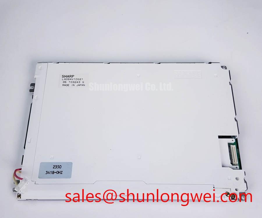
- Check the LQ084V1DG21 label against the equipment service record before disconnecting the display harness.
- With power isolated, inspect connector contacts, cable folds, mounting points, and the visible glass surface for damage or contamination.
- Prepare full-screen color patterns and a repeatable camera position to record pixel defects, background shading, and viewing-angle changes.
- Check that the mounting frame supports the module without twisting it or pressing against the active display area.
The Sharp LQ084V1DG21 is a TFT-LCD active matrix color display module in the industrial LCD/HMI category. Incoming inspection should separate module behavior from controller, harness, and illumination faults before a replacement decision is made.
| Product identification | Specification or verification requirement |
|---|---|
| Model | LQ084V1DG21 |
| Manufacturer | Sharp |
| Product category | Industrial Grade LCD/HMI Panel |
| Module construction | TFT-LCD Active Matrix Color Display Module |
| Electrical, optical, and mechanical limits | Consult Datasheet: dimensions, resolution, supply, interface, connector assignment, backlight configuration, operating temperature, and timing limits. |
Compare moving edges and gray transitions at a stabilized reference temperature before assessing cold-condition image smearing. As a Design Consideration, reduced temperature can slow liquid-crystal response, making motion trails more visible even when the controller delivers frames correctly. A stationary test image alone will not expose this behavior; include scrolling text and alternating gray fields while keeping the source timing unchanged.
Separate optical transition delay from frame-delivery problems by recording the source image and panel response together. If the controller pauses while the displayed image remains sharp, investigate the source path. If transitions stretch while source timing remains consistent, characterize the optical response. Gray-to-gray behavior depends on the starting and ending levels, so one transition cannot represent the entire display.
Outdoor readability also needs an assembled-display test. Measure white and black fields under controlled ambient illumination, retaining the intended cover window and viewing direction. Reflected light can reduce usable contrast independently of the panel’s dark-room contrast. Neither sunlight readability nor an anti-glare treatment should be inferred from the module category. Inspect color and grayscale from the intended operator positions without assigning an unverified IPS or MVA architecture to this model.
As an Engineering Recommendation, assess enclosure sealing and any proposed optical bonding at assembly level: bonding alone does not establish moisture protection. Avoid frame loading that changes background uniformity during thermal expansion, and inspect edge condition after approved environmental testing without assuming a particular sealant chemistry. The Ultimate Guide to Industrial TFT LCD Technology provides supporting integration context for evaluating thermal margins and viewing conditions.
20-Pin/30-Pin Differential LVDS Timing, Pixel Clock & Skew Compensation
Trace the equipment schematic to the panel connector before treating connector size as evidence of LVDS compatibility. The heading describes interface checks, not an established connector count or signal topology for LQ084V1DG21. Replacement assessment must follow the actual pin assignment, supply requirements, signal format, and controller timing.
As a Design Consideration, connector fit does not establish electrical interchangeability. Compare power and return contacts, signal direction, connector orientation, and cable contact side before applying power. Where the documented interface is differential, maintain pair continuity through the harness and examine discontinuities at connectors. Where it is parallel, assess data and clock relationships using that interface’s timing requirements rather than applying differential-link assumptions.
Capture power sequencing at the panel connection, including signal activity during supply transitions. Evaluate rise behavior against the applicable timing specification rather than selecting a generic ramp interval. For a documented LVDS implementation, transmitter and receiver mapping must agree; JEIDA/VESA mapping differences can alter color interpretation without a failed panel. Pixel clock, active image dimensions, and blanking also need to match the controller configuration.
Inspect grayscale ramps before changing gamma settings or timing-controller adjustments. Compressed shadow detail, clipped highlights, or color imbalance can originate in source processing as well as display behavior. Keep a known-good configuration for comparison. The LQ070Y3LW01 can be included in a separate selection review, but its link does not establish equivalent dimensions, resolution, or electrical compatibility. For either candidate, compare the complete interface and mechanical envelope.
Eye-Diagram Voltage Margin & Differential Noise Floor Verification in High-Vibration Bays
Observe image stability while independently changing cable position and nearby equipment operating state. This separates movement-sensitive connection problems from interference correlated with motor switching. Record the displayed pattern, controller output, and event timing together; horizontal bands or intermittent pixels are evidence to investigate, not proof of a particular failure.
As an Engineering Recommendation, inspect harness strain relief and connector retention before changing signal conditioning. The cable should not pull sideways on the module connector when the enclosure moves. If the documented interface is differential, assess receiver-side eye opening, common-mode behavior, and clock-to-data relationships with suitable probes. For a parallel interface, examine setup and hold relationships at the receiving connection.
Shield termination and common-mode suppression are system-level decisions. Evaluate the enclosure grounding path and cable routing first, then test any proposed suppression component for both interference reduction and signal integrity. A shielding change that improves one operating condition can also alter return paths. Use repeatable equipment states and an unchanged test image to make comparisons meaningful.
Engineers evaluating this module for an AGV operator display or forklift telematics terminal should verify vibration support, enclosure protection, viewing position, and harness retention as separate compatibility items. This is not a vehicle qualification claim. Manufacturer context is available through Sharp Devices Europe Industrial Display Solutions and the Sharp Display Solutions Official Portal; assembly-level measurements remain necessary to judge the installed display.
Full-Screen Primary Color AOI Screening: Stuck Sub-Pixels & Background Uniformity Audit
Display solid red, green, and blue fields individually, then examine white, black, and neutral-gray backgrounds under unchanged viewing conditions. Primary colors help locate subpixel anomalies; white and gray fields reveal shading and tint variation, while black helps expose unwanted light transmission. Record defect coordinates rather than relying on visual memory.
For automated optical inspection, lock camera exposure, focus, and white balance between captures. As a Design Consideration, automatic exposure can conceal brightness differences, while camera sampling can create patterns absent to the observer. Recheck suspected defects visually and with a known-good image source before assigning them to the module.
Bench Tip: Use an ESD-controlled workstation and isolate power before seating the display cable squarely and engaging its retention mechanism.
If the screen appears dark, oblique external illumination can help determine whether image content remains present. Treat that observation as a way to narrow the investigation, not as confirmation of a backlight or internal driver failure. Persistent lines likewise require comparison across test patterns, cable checks, and source configurations.
Audit brightness and color uniformity after thermal stabilization, keeping the measurement locations and viewing geometry consistent. As an Engineering Recommendation, evaluate dimming through the actual equipment controller, recording visible flicker, acoustic behavior, and brightness response across its supported settings. Do not impose a generic PWM frequency or infer a backlight lifetime from the panel category. If localized shading changes as the assembly warms, compare enclosure pressure, illumination behavior, and external thermal conditions before deciding which part requires service.


