Content last revised on October 11, 2026
Thermal Cycling Degradation of Polarizer Adhesives & Sealant Gasket Integrity
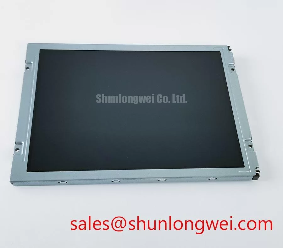
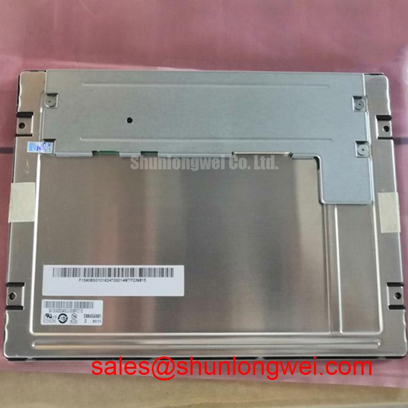
When a G084SN05-V4 shows slow image transitions, edge discoloration, or intermittent operation after cabinet temperature changes, I first separate panel behavior from enclosure stress. This model is identified as an AUO TFT-LCD Active Matrix Color Display Module; the original equipment documentation remains the controlling reference for its electrical interface, optical stack, temperature rating, and mechanical envelope.
Sub-zero operation can increase liquid-crystal viscosity and make gray-to-gray transitions appear slower. That visible delay should be assessed with a known-good display path and a repeatable image sequence rather than treated as proof of panel damage. Check the same gray transitions during warm-up and cool-down, then compare the result with the timing behavior expected by the host controller.
Perimeter gasket compression also deserves attention in industrial HMI assemblies. Uneven fastening can transfer localized stress into the display frame, while a poorly seated dust seal may permit contamination or moisture migration. For a high-voltage substation protection or SCADA dispatch console, inspect the bezel contact pattern, gasket continuity, and cable bend radius after the panel has been removed from the cabinet. The mounting frame should release mechanical load evenly instead of pressing directly on the active viewing area.
High-EMI cabinets require controlled signal routing. As a Design Consideration, differential display pairs should be routed as a balanced transmission path with continuous reference and minimal interruption at connectors. A 100 Ω differential target with a ±10% fabrication tolerance is a commonly used engineering starting point for compatible high-speed links, but the actual interface standard and permitted skew must come from the panel and controller documentation. Designers should verify signal integrity with the installed cable, connector, grounding arrangement, and enclosure before approving the assembly. The The Ultimate Guide to Industrial TFT LCD Technology provides additional reference material for display selection and integration checks.
For environmental assessment, compare the display after controlled temperature exposure with the same unit at room conditions. Look for persistent edge haze, expanding dark regions, seal separation, or a change that follows cabinet distortion rather than temperature alone. These observations help distinguish optical material aging, mounting stress, and upstream timing behavior without assigning a single cause prematurely.
Flashlight Dark-Shadow Optical Diagnostic to Isolate Logic vs. Backlight Failure Modes
A dark screen requires a controlled optical check before the panel is removed from service. Display a primary red, green, blue, white, and black sequence through the original controller, then examine whether image information remains visible under oblique flashlight illumination. A faint image under the flashlight can indicate that the image path is active while the illumination path requires further investigation; it does not by itself identify the failed circuit.
Use the flashlight at approximately 45 degrees to reduce direct reflection from the front surface. Compare the center, corners, and perimeter while changing between primary colors. A localized vertical or horizontal line that remains in the same position across colors should be documented separately from a uniform loss of illumination. COG driver or interconnect defects can produce line-related behavior, while a backlight or driver issue may leave image content present but difficult to see. Verification should include the controller output, panel connector seating, and the installed backlight circuit.
Do not assume that G084SN05-V4 uses a particular backlight technology, supply voltage, or dimming interface from the model name alone. The system integrator should verify the required supply voltage and backlight architecture from the original panel documentation. This is especially important when replacing a display in a SCADA console, where an apparently compatible mechanical panel may still have different timing or illumination requirements.
For the logic path, compare the clock and data waveform at the controller output and at the panel connector. TTL and LVDS are not interchangeable signal descriptions, and the relevant clock duty cycle, setup time, hold time, and jitter tolerance depend on the confirmed interface. Temperature can alter cable behavior and timing margin, so repeat the comparison at the operating conditions that reproduce the fault. The VESA Video Electronics Standards Association Official Portal is a useful standards reference when reviewing display signaling terminology, but it does not replace the specific panel documentation.
Backlight Driver Compatibility, Dimming and Flicker Suppression
Backlight evaluation should begin with interface identification rather than a presumption that the display accepts a particular driver topology. The available product classification identifies the G084SN05-V4 as an industrial TFT-LCD active matrix color module, but it does not establish a WLED current rating, PWM ratio, CCFL ignition requirement, or half-brightness lifetime value.
When a replacement is installed, identify the illumination connector, enable control, brightness input, and return path from the original system documentation. A constant-current LED driver must be matched to the actual backlight assembly; applying an unverified driver can create excessive current, unstable startup, or visible brightness modulation. If the system uses PWM control, observe the control waveform and the resulting optical output with an oscilloscope or photometric instrument. Audible noise should be assessed at the driver and enclosure, not attributed to the display without measurement.
Flicker evaluation is best performed at several brightness settings and with the cabinet fan, inverter, and nearby motor drives operating in their normal states. Record whether the variation follows the command signal, the supply rail, or the electromagnetic environment. The panel should not be described as having a specific dimming ratio or LED lifetime unless that value is present in the applicable AUO documentation. Product background and industrial display information can be reviewed through AUO Corporation Industrial Display & Embedded Systems.
For glove or wet-touch operation, verify the complete front assembly rather than attributing touch performance to the LCD cell. The G084SN05-V4 product classification does not confirm a resistive or capacitive touch layer, anti-glare treatment, anti-reflective coating, or wet-finger sensitivity. These features depend on the installed overlay and controller. In a dispatch console, test the actual glove material, surface contamination, viewing angle, and nearby switching equipment before accepting the interface.
Aluminum Heat Spreader Sizing & Thermal Interface Placement along Narrow Display Edges
Thermal work around a narrow display edge should protect the panel from uneven pressure as much as it manages heat. First identify the genuine heat sources in the assembly, such as the controller board, backlight driver, or cabinet-side power electronics. Do not attach a spreader directly to the active display area or use adhesive layers that change the designed mechanical loading without checking clearance.
An aluminum rail may distribute heat along a frame, but its dimensions, contact area, insulation, and attachment method must be determined from the enclosure and the confirmed panel construction. The design objective is to reduce localized hot spots while preserving gasket compression and allowing differential expansion between the display, bezel, and cabinet. Thermal interface material should remain outside optical and electrical clearances, with placement verified during vibration and thermal cycling checks.
Localized heating near an edge can accelerate visible non-uniformity, color change, or backlight degradation, but these effects should be confirmed through temperature mapping and image comparison. Do not assign an L70 or B50 value to this model without a manufacturer lifetime specification and test conditions. A useful maintenance practice is to inspect the cabinet airflow path, filter condition, connector seating, and perimeter gasket during scheduled service.
⚠️ Maintenance Note: Isolate power before disconnecting the display cable, and inspect the gasket seating whenever the panel is removed from the cabinet.
For integration into a high-voltage substation protection or SCADA dispatch console, verify the complete replacement envelope: mechanical cutout, connector orientation, host timing, backlight control, touch overlay, optical surface treatment, and enclosure sealing. The G084SN05-V4 should be evaluated as an AUO industrial LCD/HMI module within that complete system rather than by model number alone.