Content last revised on September 23, 2026
Preventing Localized Light Guide Plate Compression Warp on Dark Screen Fields
| Model | G084SN05 V8 |
| Manufacturer | AUO |
| Product Category | Industrial Grade LCD/HMI Panel |
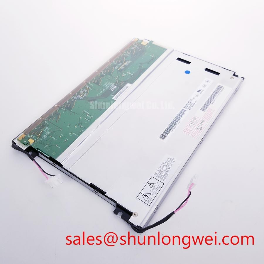
| Display Construction | TFT LCD Active Matrix Color Display Module |
| Specification Status | Verify against the applicable AUO documentation |
Inspect the powered panel on a full black image before tightening the enclosure, then watch for clouded patches, corner brightening, pressure shadows, or uneven dark fields while each fastening point is brought into contact. These optical changes can appear when the host bezel applies uneven mechanical force across the visible area of the G084SN05 V8 TFT LCD module.
The panel should sit on a flat, clean support surface with clearance around the active display area. A chassis bezel that contacts the front surface unevenly can create local pressure zones that become most visible during dark screen inspection. This is a Design Consideration for the surrounding equipment enclosure, not an AUO factory mounting specification for this model. Check the rear support points, bezel opening geometry, gasket compression, and any touch overlay stack before attributing a dark field issue to the LCD itself.
For an enclosure using M3 hardware, a cross-pattern tightening sequence with controlled torque selected from the fastener, insert, and mechanical drawing is a General Industry Design Consideration. The system integrator should validate the final fastening method against the mechanical drawing and the completed bezel assembly. Tightening one corner fully before the other corners can pull the module out of plane and make a normal backlight appear optically uneven.
Use a uniform black, gray, white, red, green, and blue test pattern while the module is installed in the intended frame. A dark field reveals pressure related mura more clearly than a bright field. A white field helps distinguish pressure marks from a localized backlight variation. If an optical mark changes as bezel screws are loosened slightly, inspect the mechanical stack first. If the mark remains unchanged with the display resting freely on a protected flat bench, document its position and compare it with a known good panel where available.
Signal quality should also be checked when visual artifacts occur near a particular image region. Clock jitter, data hold time, connector contact resistance, and cable motion can create image instability that is visually different from pressure mura. Verify the transmitter waveform and data timing across the actual equipment temperature range. This is an Engineering Recommendation because display timing performance is determined by the host controller, the interconnect, and the configured interface rather than by the panel enclosure alone.
For CNC operator panels and robot teach pendants, screen replacement work should preserve the original display support arrangement. A replacement panel can be evaluated for mechanical fit, connector orientation, display interface, and optical behavior, but matching diagonal size alone does not establish interchangeability. When another panel is under review, TCG084SVLQAPNN-AN30-S can be assessed as a separate option through documented electrical, optical, and mechanical comparison.
Controlled 100 Ohm Differential Impedance Flex Routing to Suppress High Frequency Jitter
Probe the display data path at the host connector when a split image, intermittent vertical disturbance, or unstable picture appears after cable movement. These symptoms can arise from poor connector engagement, damaged flex conductors, unsuitable differential routing, timing mismatch, or an issue elsewhere in the host display chain. Inspect each possibility instead of assigning a single cause from the visible symptom.
The G084SN05 V8 is identified as a TFT LCD active matrix color display module. The system integrator should verify the required supply voltage, connector pin assignment, interface format, and data mapping from the original panel documentation before connecting a replacement. Do not select between 3.3 V and 5.0 V logic assumptions without confirming the original equipment requirements. Incorrect supply or mapping assumptions can produce a blank image, abnormal color ordering, or unstable operation.
Where the host design uses differential display signaling, controlled 100 Ohm differential impedance is a Design Consideration for the cable and PCB route. The objective is to maintain signal integrity between the transmitter and panel connector, particularly where the equipment includes long internal harnesses, moving cable carriers, switching power supplies, or high noise motor drives. Route differential conductors consistently, avoid unnecessary discontinuities, and verify the result with appropriate test equipment against the known good signal path.
JEIDA and VESA mapping differences require particular attention during panel replacement. A display that presents unusual color order, color intensity changes, or a divided image may indicate mapping incompatibility, but similar behavior can also result from missing data pairs or poor connector contact. Confirm the original controller output format and the panel input requirement as a matched pair. Do not alter mapping configuration on the basis of a single visual symptom.
Power sequencing is equally important. The host power rail should rise, stabilize, and be evaluated against the original equipment timing requirement before display data are enabled. A panel that starts with a white image, retains a transient image during shutdown, or initializes inconsistently should be investigated with an oscilloscope at the panel supply and signal enable points. The required rise time and sequencing order are system determined and must be verified against the original documentation.
Cold ambient operation can visibly slow liquid crystal response. At low temperature, transitions between gray levels can appear less responsive, and moving interface elements may show temporary blur or trailing. This behavior should be separated from electrical data corruption by testing a static pattern and a moving pattern under the same conditions. If the equipment uses a heater strip or thermal control assembly, evaluate its controller behavior, sensor placement, and enclosure heat flow as part of the complete HMI system.
💡 Bench Tip: Disconnect power and use ESD protection before handling the display cable, then insert the flex perfectly level and confirm the connector lock is fully closed without forcing the cable.
Super IPS / MVA Wide Symmetric Viewing Cone 85/85/85/85 for Multi Angle Consoles
View a neutral gray image from above, below, left, and right while the panel is mounted at its intended operator angle, then record whether contrast, grayscale order, or color balance changes with direction. This practical check identifies whether the visible behavior suits the equipment viewing position and whether any perceived issue comes from the panel, the protective window, ambient reflections, or the host image settings.
The supplied factory information identifies G084SN05 V8 as an industrial TFT LCD active matrix color display module, but it does not establish a Super IPS, MVA, or 85°/85°/85°/85° viewing specification. Those figures must not be assigned to this model without the corresponding AUO optical specification. Wide viewing performance should therefore be verified from the original panel documentation and by controlled inspection of the actual installed display.
TN type displays can show directional grayscale or contrast changes that are more apparent from certain viewing angles. IPS and MVA technologies are commonly evaluated where more symmetric viewing is required, but technology names alone do not guarantee a particular viewing result for a given panel. For a robot teach pendant, the practical question is whether the displayed alarm text, axis information, and touch interface remain readable from the operator positions required by the machine design.
Surface reflections can obscure a mechanically and electrically correct display. Inspect the front stack under the actual workplace lighting condition, including overhead fixtures and nearby windows. An anti glare surface can reduce distinct reflections, while a glossy surface may provide different apparent contrast in controlled light. The front cover lens, touch overlay, air gap, bezel depth, and panel surface each affect the final viewing result. These are enclosure level Design Considerations rather than verified AUO specifications for this module.
Run a grayscale ramp and color test image at several brightness settings supplied by the original equipment. If a visual issue occurs only through the front window, remove the enclosure influence during controlled bench inspection where service procedures permit. If the issue remains with the panel outside the host assembly, inspect the input image data and compare the panel behavior with the same source signal on a known good assembly.
Industrial HMI integration should account for operator position, ambient illumination, protective cover selection, and expected display content. Static text pages, alarm screens, and machine status graphics can expose poor contrast more readily than moving graphics. For broader evaluation of panel technology, optical behavior, and selection limits, refer to The Ultimate Guide to Industrial TFT LCD Technology.
Full Screen Primary Color AOI Screening: Stuck Sub Pixels & Background Uniformity Audit
Display full red, green, blue, white, gray, and black patterns at the native controller output during incoming inspection, then examine the entire active area from normal viewing distance and close range. This screening method helps reveal persistent bright points, dark points, colored sub pixel behavior, line disturbances, and nonuniform background regions before the panel is installed into a finished HMI assembly.
Begin with black because it makes unwanted light leakage, bright pixels, and localized glow easier to observe. Move to white and gray for background uniformity inspection, then use red, green, and blue fields to identify a sub pixel that does not follow the commanded image. Photograph any repeated feature using the same exposure and viewing angle so that later comparison is meaningful. A single observed point should be documented carefully rather than classified from an unrepeatable visual impression.
A 45 degree flashlight inspection can help distinguish a front surface mark, cover lens contamination, or shadow effect from an internally visible image defect. Perform this test with the panel safely de energized where access allows. A defect that changes strongly with an external light angle may be associated with the outer display stack, while a line or pixel feature that remains fixed across uniform test patterns may warrant further electrical and mechanical inspection. This check is diagnostic only and does not prove a specific internal failure mechanism.
Inspect the flex cable path for sharp bends, strain at the connector edge, crushed insulation, or repeated motion near a hinge point. Flex reliability depends on routing radius, restraint method, connector alignment, and service handling. Keep the cable clear of screw bosses and bezel edges, and ensure the connector latch carries the intended retention load rather than the conductive traces. A cable that looks intact can still require continuity and signal verification when the image changes during movement.
Where a differential display interface is used, characteristic impedance control and pair to pair timing alignment are Engineering Recommendations for the host assembly. A route designed around 100 Ω ± 10% differential impedance and a skew budget of 50 ps or less can be used as a qualification reference when appropriate to the transmitter and panel interface requirements. The final routing acceptance criteria must be set by the system engineer after checking the actual transmitter, cable, connector, and panel documentation.
For long term industrial HMI operation, review static image behavior with the actual user interface rather than leaving a single high contrast test image displayed indefinitely. Screen retention behavior depends on panel technology, operating condition, image content, and system use pattern. Designers should provide suitable interface management through the host system where needed, while repair technicians should verify that apparent retention is not caused by a stale controller frame, incorrect power down sequence, or unchanged source image.