

Content last revised on May 3, 2026
QM20TB-H IGBT Module: Data for Thermal Design & Reliability
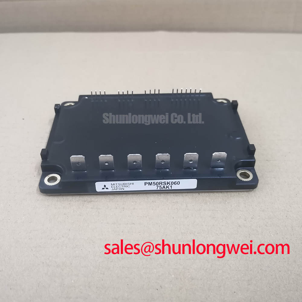
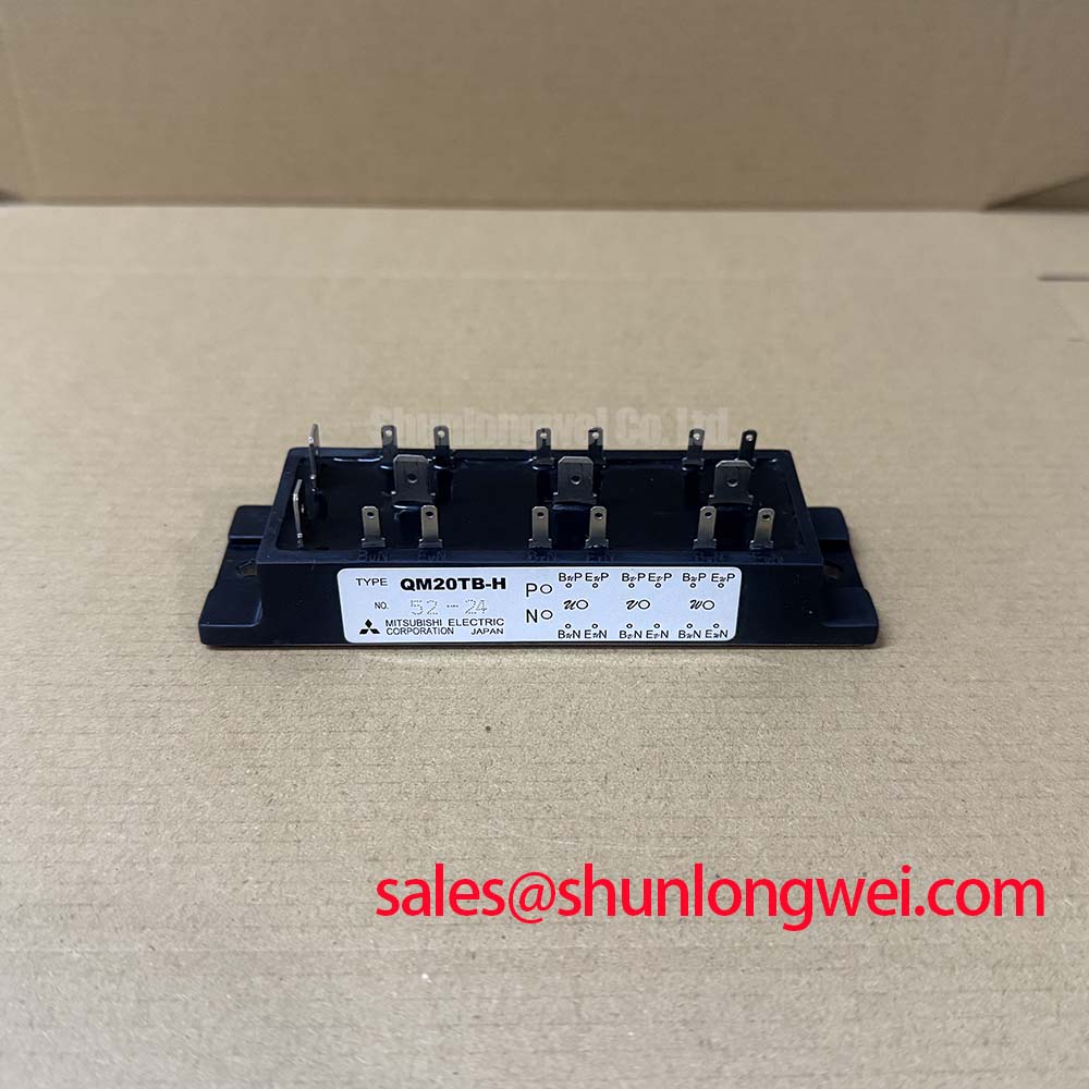
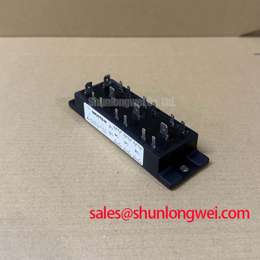
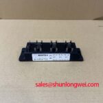
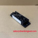
Engineered for sustained thermal performance, the Mitsubishi QM20TB-H is a six-element transistor module delivering robust power handling for industrial drive systems. It integrates six N-channel IGBTs and six free-wheeling diodes into a single, thermally efficient package. How does the module's construction contribute to system longevity? Its design prioritizes low thermal resistance, ensuring efficient heat evacuation from the semiconductor junctions, which is a cornerstone of operational reliability under continuous load conditions.
Top Specs: 600V | 20A | Rth(j-c) 1.8°C/W per Transistor
Key Benefits: Enhanced thermal stability. Simplified system assembly.
Analyzing the Thermal Pathway: A Look Inside the QM20TB-H
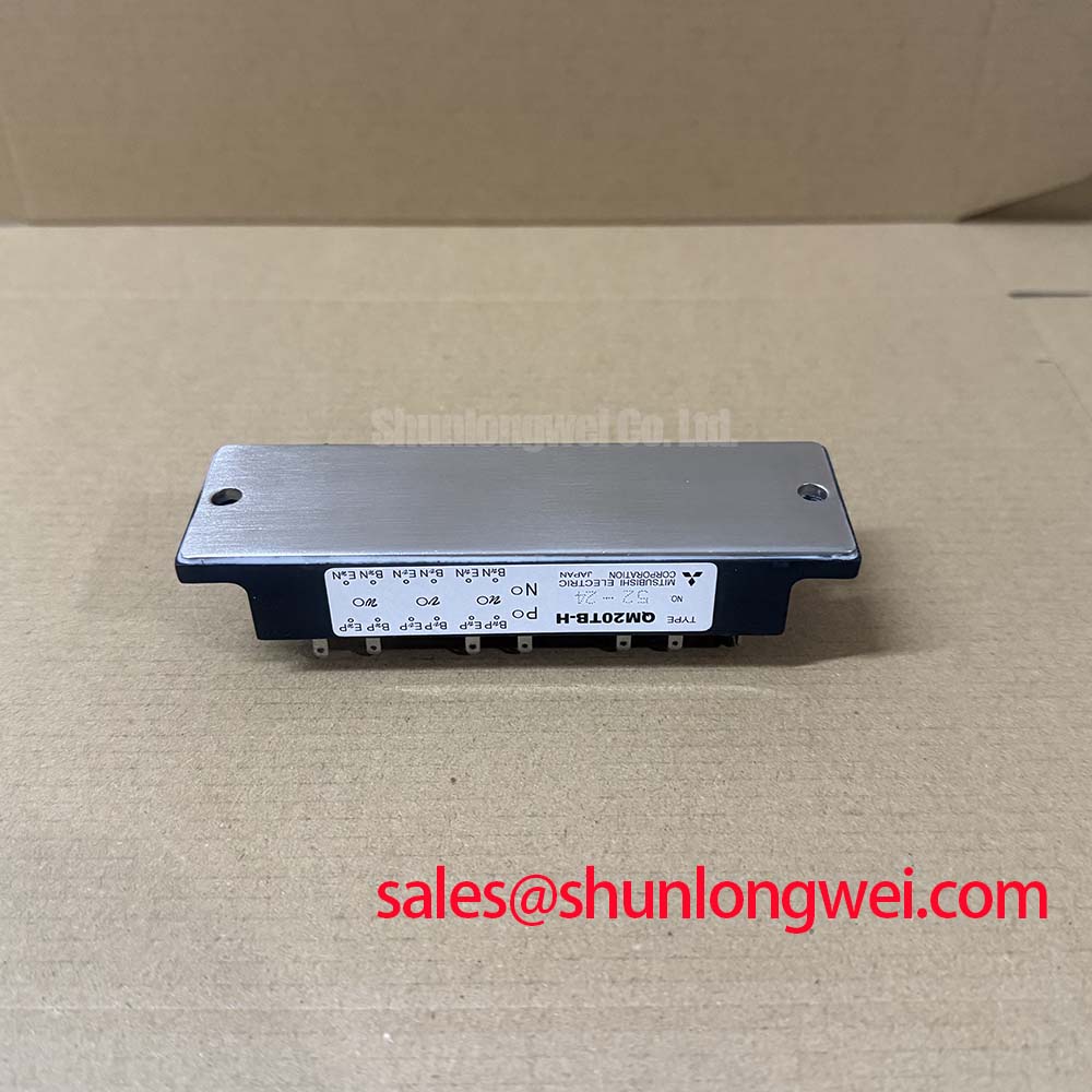
The operational endurance of any power module is fundamentally tied to its ability to manage heat. The Mitsubishi QM20TB-H is structured to provide an effective thermal pathway from the IGBT and diode chips to the system's heatsink. The specified maximum junction-to-case thermal resistance (Rth(j-c)) of 1.8°C/W for each transistor is a critical parameter for thermal modeling. This value quantifies the thermal impedance; much like a narrow pipe restricts water flow, a high thermal resistance value restricts heat flow. The low Rth of this module facilitates rapid heat transfer, keeping the junction temperature (Tj) within its 150°C maximum operating limit and mitigating the risk of performance degradation over the component's lifespan.
Furthermore, the module's 2500V isolation voltage (Viso) for 60 seconds ensures robust electrical separation between the power circuit and the mounting baseplate. This electrical isolation is crucial for safety and for preventing ground loop issues in complex industrial machinery, contributing to the overall reliability of the end system.
Powering Systems Where Uptime is Paramount
The QM20TB-H is designed for three-phase power conversion stages in applications where consistent performance is a primary engineering objective. Its electrical and thermal characteristics make it a suitable component for a range of industrial systems.
- General Purpose Inverters & VFDs: The module's 600V collector-emitter voltage (VCES) and 20A continuous collector current (IC) ratings are well-matched for controlling small to medium-sized AC induction motors in variable frequency drives (VFDs).
- Servo Drives: In robotics and CNC machinery, precise motor control is essential. This module provides the switching foundation for servo drives that demand high reliability and consistent operation cycle after cycle. For more insights into this application, you can explore the role of IGBTs in robotic servo drives.
- Uninterruptible Power Supplies (UPS): The module's ability to handle continuous current makes it a dependable choice for the inverter stage of UPS systems, ensuring a stable power output during mains failure.
For AC drives up to 5kW requiring long-term dependability, the QM20TB-H's 1.8°C/W Rth(j-c) per transistor provides an optimal thermal foundation.
Data-Informed Component Evaluation
To support your design and evaluation process, this section provides a factual comparison based on key electrical parameters. The selection of a power module involves trade-offs between various specifications, and this data is presented to aid in a comprehensive technical assessment. Please note, this information is for engineering evaluation purposes only and does not constitute a direct recommendation.
When evaluating alternatives, it is crucial to consider the collector-emitter saturation voltage (VCE(sat)), as it directly impacts conduction losses. The QM20TB-H specifies a maximum VCE(sat) of 2.7V at its nominal current. For systems where switching frequency is higher, examining a component with different VCE(sat) and switching energy characteristics, such as the QM50DY-H, may provide relevant data points for a complete analysis.
Meeting Reliability Standards in Modern Industrial Automation
The drive towards Industry 4.0 places immense pressure on component-level reliability. Unscheduled downtime in automated manufacturing lines or logistics centers can lead to significant financial and operational consequences. Power modules like the QM20TB-H form the core of the motor drives that power these automated systems. Their long-term performance is not an option but a prerequisite. The emphasis on thermal management within the module's design directly addresses this industry need. By ensuring the semiconductor junctions operate at cooler temperatures, the module helps extend the mean time between failures (MTBF) of the entire drive, contributing to a lower total cost of ownership (TCO). A deeper understanding of common failure modes can be found in our guide to IGBT failure analysis.
QM20TB-H Technical Specifications for System Modeling
The following parameters are extracted from the official datasheet to facilitate accurate system simulation and design. A complete datasheet is available for download for full electrical characteristics and performance curves.
| Parameter | Value | Engineering Significance |
|---|---|---|
| Collector-Emitter Voltage (VCES) | 600 V | Defines the maximum voltage the device can block, providing a safety margin for systems operating on 200-240V AC lines. |
| Continuous Collector Current (IC) | 20 A | Specifies the maximum continuous current each IGBT can handle at a case temperature (Tc) of 25°C. |
| Collector-Emitter Saturation Voltage (VCE(sat)) | 2.7 V (Max) | Indicates the voltage drop across the transistor when fully on. Lower values translate to lower conduction losses and less heat generation. |
| Thermal Resistance, Junction to Case (Rth(j-c)) | 1.8 °C/W (Per Transistor) | A primary indicator of thermal performance. This low value allows for efficient heat transfer to the heatsink, crucial for reliability. |
| Isolation Voltage (Viso) | 2500 Vrms | Represents the dielectric strength between the terminals and the mounting base, ensuring electrical safety and system integrity. |
From Concept to Field: Integration Snapshots
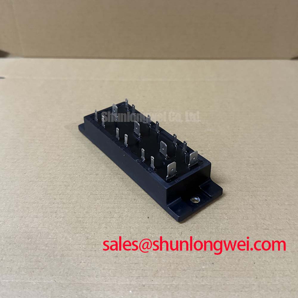
The QM20TB-H's standardized package with M4 screw terminals simplifies the assembly process. This allows for secure and reliable electrical connections, reducing assembly time and minimizing the risk of contact failure due to vibration in industrial environments. How does the QM20TB-H ensure thermal reliability? Through its low junction-to-case thermal resistance for efficient heat removal. The module’s integrated six-pack topology also reduces the number of components required for a three-phase inverter bridge, streamlining both the printed circuit board (PCB) layout and the mechanical mounting arrangement. What is the collector-emitter voltage rating? The QM20TB-H is rated for a VCES of 600V, making it suitable for a wide array of low-to-medium voltage applications.
Frequently Asked Questions about the QM20TB-H
1. What is the significance of the 'H' suffix in the QM20TB-H part number?
In Mitsubishi Electric's nomenclature, the 'H' suffix typically denotes the H-Series of modules, which were developed for high power and high reliability in general-purpose applications, featuring specific generations of IGBT chip technology and package design.
2. How do I calculate the required heatsink performance for the QM20TB-H?
To determine the required heatsink thermal resistance (Rth(c-a)), first calculate the total power dissipation (P_total) from conduction and switching losses. Then, use the formula: Rth(c-a) = (Tj_max - Ta_max) / P_total - Rth(j-c) - Rth(c-s), where Tj_max is the maximum junction temperature, Ta_max is the maximum ambient temperature, Rth(j-c) is the module's thermal resistance, and Rth(c-s) is the thermal interface material's resistance. For detailed calculations, it's essential to consult our resource on unlocking IGBT thermal performance.
3. During assembly, what are the key considerations for mounting the QM20TB-H to ensure optimal thermal contact?
Proper mounting is critical. Ensure the heatsink surface is flat and clean. Apply a thin, uniform layer of thermal interface material (TIM) to eliminate air gaps. Tighten the M4 mounting screws to the torque specified in the datasheet (typically 0.98 ~ 1.96 N·m) using a calibrated torque wrench to ensure even pressure without warping the baseplate.
4. What is the isolation voltage of this module and why is it important for motor drive applications?
The QM20TB-H has an isolation voltage rating of 2500Vrms. This is vital in motor drives as it provides a robust barrier between the high-voltage power circuit and the grounded, user-accessible parts of the machine, ensuring operator safety and protecting control electronics from high-voltage faults.
5. Can I parallel QM20TB-H modules for higher current applications?
While paralleling IGBT modules is possible, it requires careful design considerations to ensure proper current sharing. This includes matching VCE(sat) characteristics, ensuring symmetrical busbar layouts, and potentially using separate gate resistors for each module. For new designs requiring higher current, evaluating a single module with a higher native current rating is often a more reliable approach.
For engineers designing next-generation motor drives or power supplies, the focus extends beyond immediate performance to long-term operational integrity. The QM20TB-H provides a component foundation where thermal considerations are addressed at the module level. This allows design teams to concentrate on optimizing system-level efficiency and control logic, with the assurance that the core power stage is built upon a thermally sound and reliable platform provided by a manufacturer like Mitsubishi Electric.