



Content last revised on September 21, 2026
SKM150GB12T4GH13 Operational Boundaries: Insulation Barrier Integrity and Limits
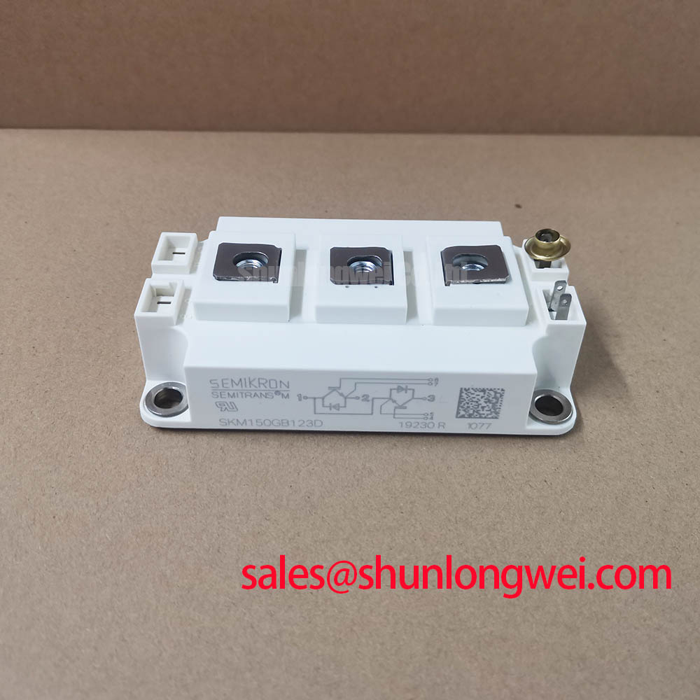
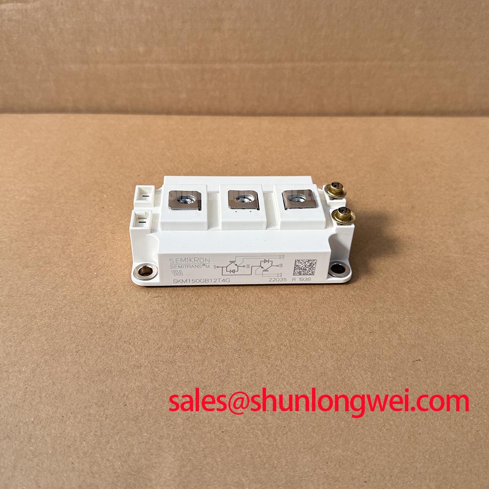
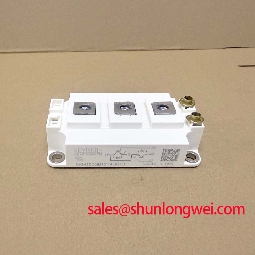
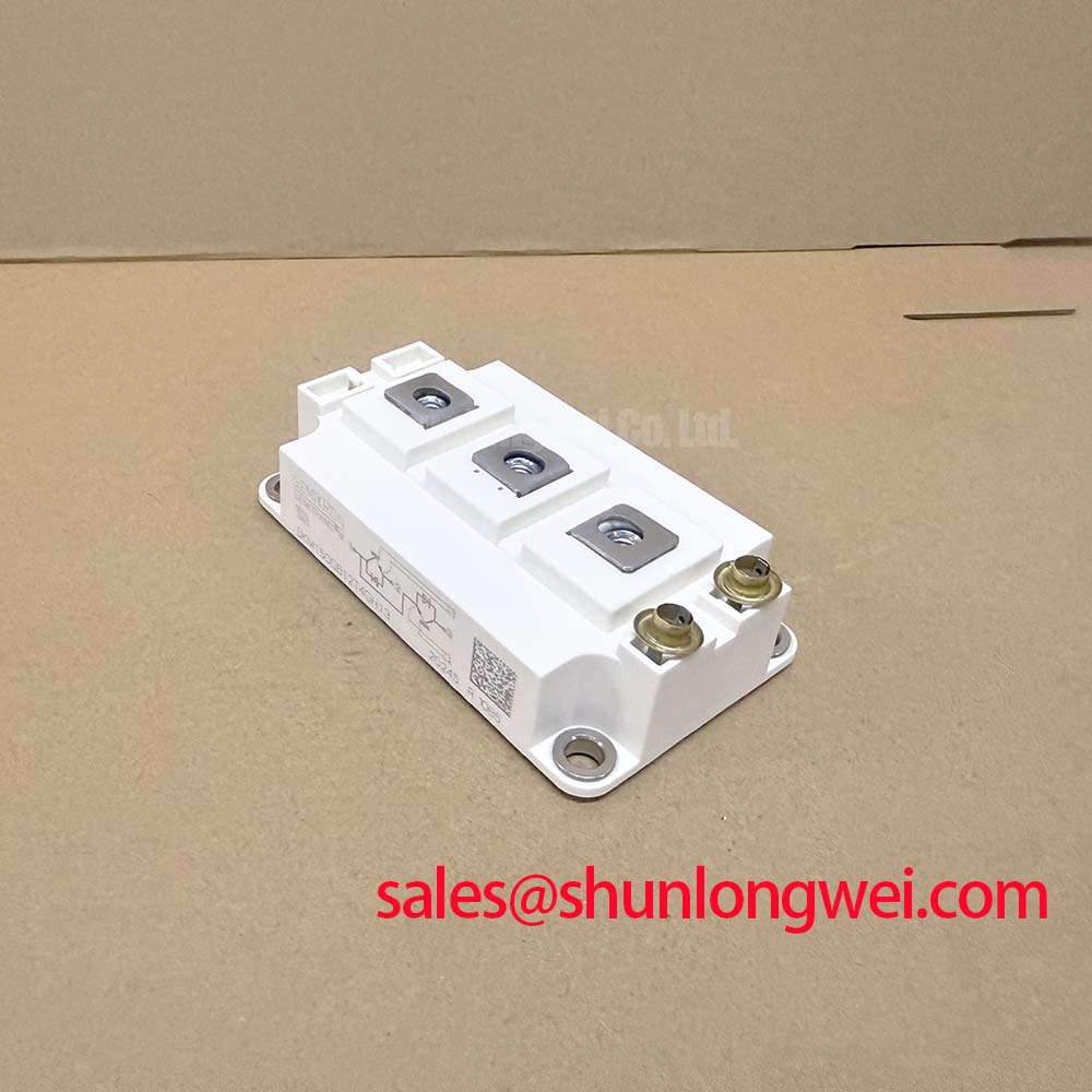
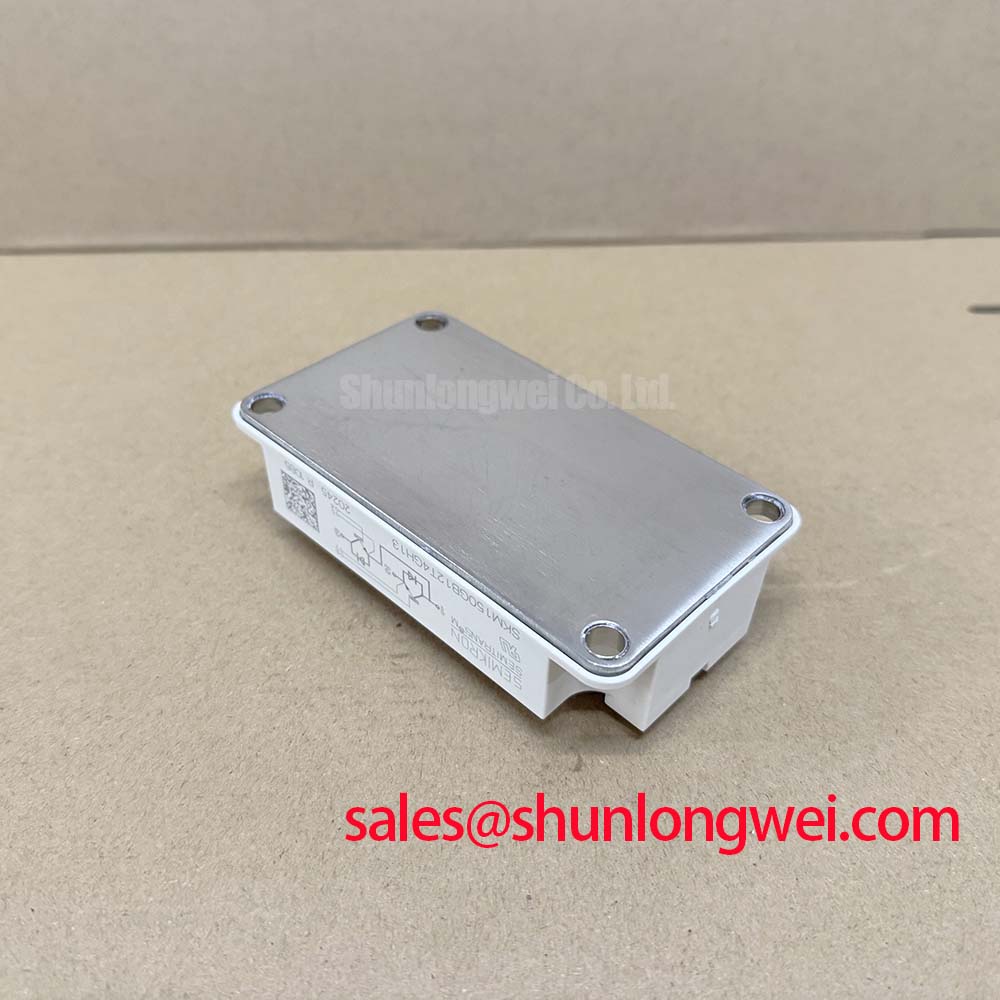
Before reconnecting the power stage, verify the module nameplate against the inverter service record and inspect the terminal area, baseplate, and surrounding insulation hardware for tracking, contamination, loose hardware, or moisture residue. The SKM150GB12T4GH13 is a Semikron IGBT module rated at VCES = 1200 V and IC = 150 A at TC = 80 °C, according to the official specification. These ratings define the module’s electrical identity; they do not define the permitted DC link, switching transient amplitude, gate drive settings, or overload duration of a complete converter.
| Official Datasheet Specification | Value |
|---|---|
| Collector Emitter Voltage, VCES | 1200 V |
| Continuous Collector Current, IC at TC = 80 °C | 150 A |
| Junction to Case Thermal Resistance per IGBT, Rth(j c) | 0.16 K/W maximum |
| Isolation Voltage, AC for 1 minute | 2500 V |
The specified 2500 V AC for 1 minute isolation rating is an official module qualification value. It should not be interpreted as a declared reinforced insulation classification, a system isolation rating, or a guarantee of common mode transient immunity for an assembled gate driver. Isolation coordination depends on the installed driver, transformer or digital isolator, printed circuit board spacing, connector arrangement, enclosure condition, and the applicable system standard.
Design Consideration: keep the high voltage power path physically separated from gate command and measurement paths, especially where switching nodes cross between control boards and the power assembly. If unexplained gate pulses appear during switching, inspect return current routing, shield termination, connector seating, and the isolation device’s documented common mode transient rating. Oscilloscope measurements should be compared with a known stable channel and taken with a probing method suitable for high voltage switching environments.
For commercial string inverter and micro grid energy storage evaluations, technicians should verify actual bus voltage, environmental contamination level, enclosure sealing, and condensation control before treating the module as a suitable service replacement. The module rating alone cannot validate insulation margins in the complete cabinet.
Transient Dynamics and Electrical Design: Multi Module Parallel Current Sharing on SKM150GB12T4GH13
When multiple IGBT positions are paralleled in a power stage, begin by confirming that the modules are electrically equivalent, mounted to comparable thermal paths, and driven from symmetrical gate loop layouts. In steady operation, the positive temperature characteristic commonly associated with IGBT conduction behavior can assist static current sharing. Dynamic sharing remains dependent on gate loop impedance, driver timing, DC link geometry, and the individual switching behavior of the installed modules.
Use matched physical routing from each driver output to its gate and emitter reference connection. A long or asymmetric return path can create unequal switching delay and ringing, causing one position to carry disproportionate transient current even where DC current sharing appears acceptable. Engineering Recommendation: minimize parasitic loop inductance where turn off overshoot and gate oscillation are observed, then verify peak voltage and current margins during representative switching tests.
Desaturation response and controlled turn off behavior
A desaturation circuit can provide an important fault indication when collector emitter voltage remains elevated after the gate command has requested conduction. The allowable short circuit response time, blanking arrangement, desaturation threshold, and shutdown profile must be determined from the complete driver design and the relevant module documentation. The supplied official parameters for this model do not establish a short circuit withstand interval or a mandatory desaturation timing.
Where the driver uses staged soft turn off, verify that its energy handling and timing are appropriate for the measured commutation loop and DC link conditions. A shutdown waveform that is too abrupt can increase inductive voltage stress, while an excessively slow response can increase fault energy. Evaluate both conditions on the actual assembly rather than assigning a universal gate resistor or protection delay.
During broader power stage repair assessment, a SKM100GB063D may be encountered in related rectifier or complementary converter positions. Its role, terminal arrangement, voltage class, thermal interface, and drive requirements must be checked independently before any system level decision.
For hardware compatibility research, the SKM75GB07E3 can be reviewed as another Semikron IGBT module reference. It is not an automatic substitute for the SKM150GB12T4GH13; procurement and maintenance teams should compare electrical ratings, circuit function, mechanical fit, and qualified driver behavior against the original equipment requirements.
Field Diagnostics and Commissioning: Thermal Time Constants and Peak Junction Assessment
After power stage installation, commission the assembly by recording heatsink condition, airflow direction, terminal tightness, and temperature behavior under controlled load steps. The official maximum junction to case thermal resistance is 0.16 K/W per IGBT. This value describes a junction to case thermal boundary and does not include thermal interface material, heatsink spreading resistance, airflow performance, cabinet temperature, or intermittent overload duty.
Peak junction assessment in pulsed service requires the manufacturer’s applicable transient thermal impedance information and the system’s measured loss waveform. A multi branch thermal model can represent how junction temperature responds over different pulse durations, but a reliable calculation needs switching loss, conduction loss, pulse profile, case temperature, and the appropriate thermal impedance curve. Without those inputs, assigning a peak junction temperature or overload capability would not be technically defensible.
Field observations can still identify practical risks. A rising temperature difference between similar parallel positions may indicate uneven clamping pressure, restricted airflow, aged thermal material, unequal electrical loading, or a measurement issue. Check the complete chain before attributing the result to the module itself. Inspect cooling fins and fan paths for dust accumulation, confirm that air recirculation is not heating the inlet stream, and repeat temperature readings after the equipment reaches a stable operating condition.
⚠️ Maintenance Note: Periodically monitor terminal and heatsink contact temperature rise, then clean the airflow path and recheck mounting hardware during planned maintenance.
The Semikron Danfoss discussion of sintering technology provides useful industry context on thermal packaging approaches, but it should not be used to infer unlisted construction details or lifetime performance for this specific module.
Engineers evaluating resonant or inverter switching arrangements can also review Resonant Topologies in Home Appliances for topology level context. Switching topology analysis does not replace qualification testing of the actual commercial inverter or energy storage power stage.
SKM150GB12T4GH13 Circuit Protection and Reliability: Calibrating Thermal Interface Material Thickness Uniformity
Remove hardened, contaminated, or uneven thermal material from the heatsink and module contact surfaces using a controlled cleaning process that does not damage the baseplate or leave abrasive residue. Apply fresh thermal interface material uniformly across the mounting area and inspect for gaps before final tightening. Design Consideration: a thin, continuous thermal interface layer in the approximate 50 to 100 μm range is commonly used as a starting integration practice, subject to the thermal material supplier guidance, baseplate flatness, and equipment manufacturer requirements.
Do not compensate for baseplate curvature or heatsink damage by applying an excessive amount of thermal compound. A thick or nonuniform layer can increase thermal resistance and create inconsistent temperature distribution between devices. Place the module carefully, avoid sliding it across the interface after seating, and tighten mounting screws in a balanced sequence so clamping force develops progressively across the baseplate.
Terminal hardware also deserves inspection during maintenance. Verify conductor alignment, terminal surface cleanliness, and screw condition before tightening. The correct mounting torque, screw grade, washer arrangement, and terminal torque must come from the module documentation and the original equipment mechanical specification. These values are installation dependent and should not be assumed from another module family.
In humid industrial environments, inspect cabinet seals, cable glands, cooling paths, and idle equipment for signs of condensation. Moisture control, periodic dust removal, and repeatable clamping practice help preserve the external electrical and thermal interfaces around the SKM150GB12T4GH13.