



Content last revised on September 20, 2026
Field Diagnostics & Commissioning: Semiconductor Protection Fuse Selection in TT92N14KOF Topologies
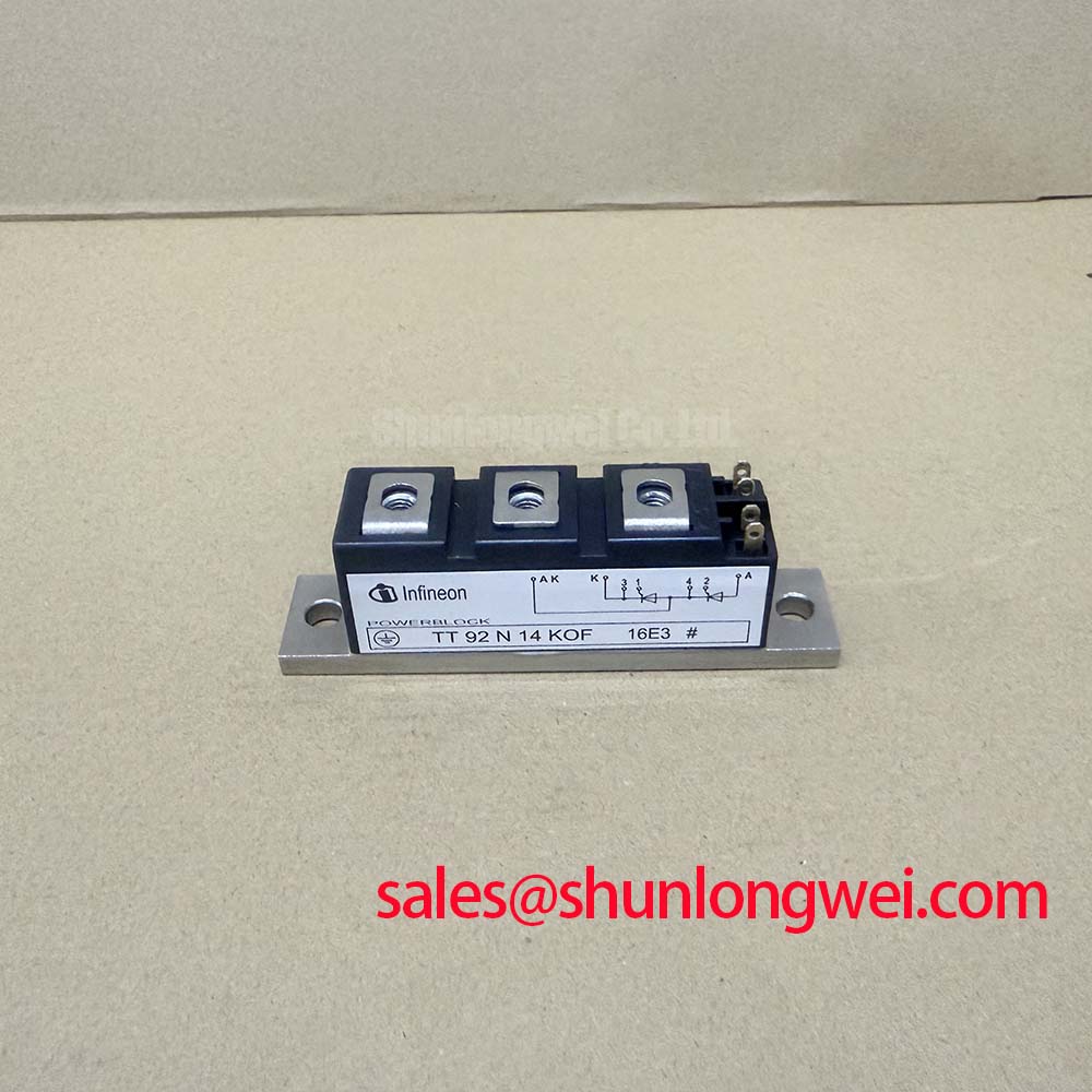
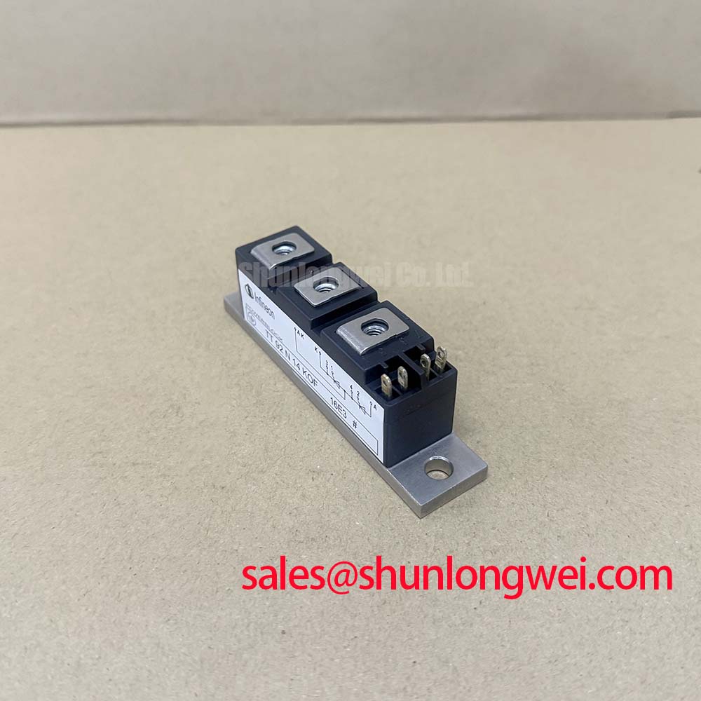
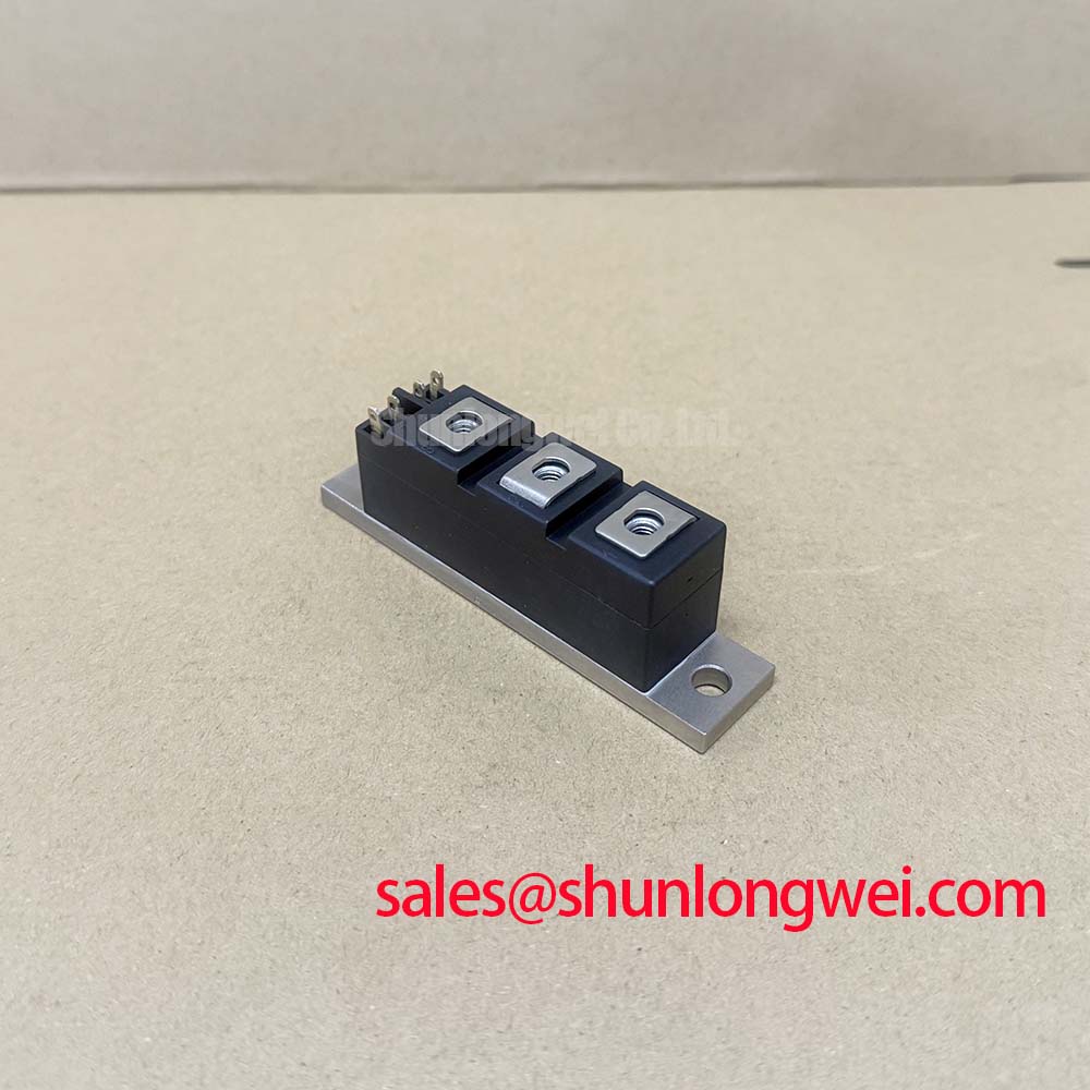
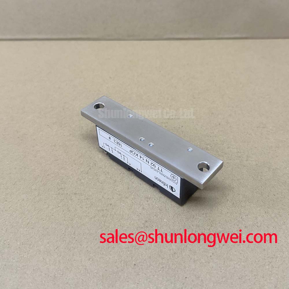
With the power isolated, first verify the module marking, terminal condition, heatsink contact area, and the equipment’s recorded voltage and current limits before reconnecting a TT92N14KOF dual thyristor module. This Infineon device is rated at 1400 V VRRM and 92 A ITAVM at TC = 85 °C, both Official Datasheet Specifications. Its specified isolation voltage is 3000 V RMS at 50 Hz for 1 s, while the operating junction-temperature range is −40 to 125 °C.
| Official Datasheet Specification | Value |
|---|---|
| Repetitive peak reverse voltage, VRRM | 1400 V |
| Average on-state current, ITAVM at case temperature 85 °C | 92 A |
| Isolation voltage, VISOL, 50 Hz RMS, 1 s | 3000 V |
| Thermal resistance, junction to case, per thyristor | 0.30 K/W |
| Operating junction temperature, Tvj op | −40 to 125 °C |
In a phase-controlled power assembly, the semiconductor fuse must be checked as a coordinated protection element rather than treated as a general feeder fuse. The TT92N14KOF rating establishes the electrical boundary, but it does not publish a universal fuse choice. Engineers should compare the fuse manufacturer’s pre-arcing and total-clearing I²t information against the thyristor module documentation and the actual prospective fault current of the installation.
For a high-voltage three-phase motor solid-state soft starter, inspect each phase branch for equal terminal engagement, correct fuse placement, and adequate clearance to adjacent conductive hardware. A fuse that clears too slowly can allow destructive fault energy to reach the semiconductor path; a fuse selected without evaluating normal starting current can cause unnecessary service interruption. These are system coordination checks, requiring verification against the original controller schematic and protection documentation.
⚠️ Field Alert: De-energize, discharge the connected system, and confirm absence of hazardous voltage before loosening power terminals or removing the module from its heatsink.
Mounting torque, conductor hardware, and fuse-holder torque are Design Considerations, not published TT92N14KOF specifications here. Follow the module drawing, hardware supplier documentation, and equipment service procedure rather than transferring torque values from another package.
TT92N14KOF Circuit Protection & Reliability: Calibrating Turn-On Current Rise Limiting
The 0.30 K/W junction-to-case thermal resistance per thyristor is an Official Datasheet Specification that supports thermal-path assessment, yet it does not define permissible transient current rise or an RC snubber value. Snubber capacitance, resistance, and any series saturable reactor should be selected from measured commutation behavior, line conditions, and the controller’s intended firing sequence.
Design Consideration: minimize parasitic inductance in the main current loop and keep the trigger circuit physically separated from high-current conductors where practical. This helps reduce transient coupling that can disturb a phase-control signal during turn-on or commutation. Confirm the result with suitably rated differential measurements at the installed assembly, checking peak voltage against the device’s applicable specified voltage ratings and transient limits.
The dual-thyristor topology should also be reviewed for symmetrical phase connections. Uneven busbar geometry or unequal thermal interfaces can influence current sharing between parallel paths in the surrounding system. 💡 Pro Tip: Use a symmetrical power-bus layout where possible, then validate turn-on and turn-off transients with controlled commissioning tests.
For broader test sequencing and evidence-based fault isolation methods, consult the Field Engineer’s Handbook.
Preventing Spurious Faults: Phase-Controlled Rectification and Firing-Angle Guidelines for TT92N14KOF
Phase-controlled rectification changes the transferred AC energy as firing angle changes. At earlier firing positions, the thyristor conducts for a larger portion of the available sinusoidal waveform. As the firing angle advances toward the later part of the half-cycle, delivered average DC output reduces while displacement effects and reactive-power demand become more significant at the system level.
For a motor soft starter, firing-angle control should be validated across the intended acceleration profile rather than assessed from a single steady-state waveform. Trigger pulse timing, phase reference integrity, and the load response can each affect whether all controlled paths behave consistently. Oscilloscope traces from a known-good phase offer a useful comparison point when a branch appears to fire late, commutate unexpectedly, or deliver unequal current.
The TT92N14KOF operating range of −40 to 125 °C is an Official Datasheet Specification, but controller timing stability and isolation performance remain properties of the complete equipment. Designers should verify creepage and clearance, trigger isolation, and common-mode transient tolerance according to the equipment’s voltage architecture and applicable standards. For context on Infineon power-semiconductor technology, see the Infineon OptiMOS™ Low Voltage MOSFET portfolio; it is a separate product family and does not define TT92N14KOF characteristics.
When an installed unit requires cross-reference review, TT570N16 can be assessed against the original circuit requirements, terminal arrangement, thermal interface, voltage rating, current rating, and firing conditions. Compatibility must be established by the system engineer before installation.
TT92N14KOF Operational Boundaries: Evaluating Thermal Avalanche Margins during High Peak Limits
Do not infer a 10 ms half-cycle surge current rating, avalanche capability, or allowable repetitive overload condition from the listed continuous-current rating. These limits require the applicable manufacturer data for the exact module and the actual fault-waveform conditions. The published 92 A average on-state current at TC = 85 °C must not be treated as a substitute for surge-current verification.
During service investigation, document heatsink flatness, interface-material condition, airflow condition, measured case temperature, and evidence of loose terminal hardware. The stated 0.30 K/W per-thyristor junction-to-case resistance only describes one section of the thermal route; the complete thermal result also depends on the mounting interface and heatsink performance. Engineers should verify junction-temperature margin under the real duty cycle before restoring reverse voltage following overload events.
For reliability-oriented system evaluation, avoid assumptions about lifetime, insulation endurance, electromagnetic compliance, or fault survivability without supporting equipment-level evidence. Information on interconnect-focused semiconductor developments is available in Infineon’s .XT Technology article, although it does not establish performance limits for this thyristor module.