


Content last revised on March 30, 2026
FS400R07A1E3: Engineering High-Reliability Automotive Power Conversion
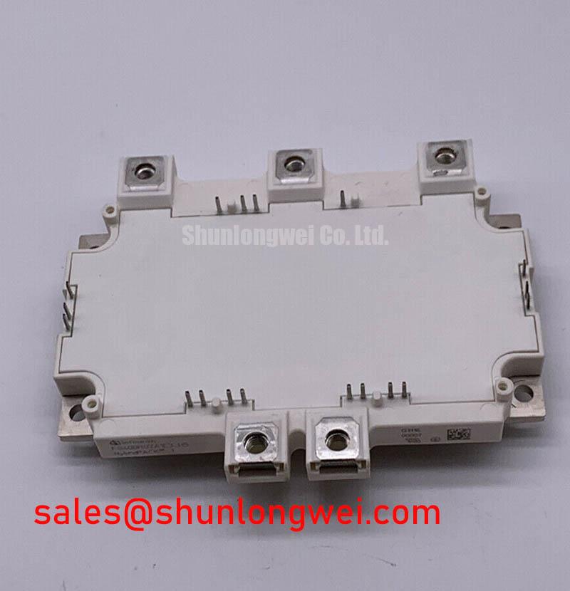
How do you guarantee robust thermo-mechanical stability in a 30kW hybrid electric vehicle (HEV) inverter operating under severe under-the-hood conditions? The architectural solution lies in the specific substrate and die integration of the FS400R07A1E3, a HybridPACK™ 1 module by Infineon. This device leverages a Six-Pack configuration of Trench-Field-Stop IGBT3 and Emitter Controlled 3 diodes to deliver automotive-grade reliability and optimized thermal management for mild hybrid powertrains. With core specifications of 650V, 400A, and an extremely low VCE(sat) of 1.45V (typ), it guarantees minimized thermal resistance and proven long-term performance. Addressing a critical engineering concern, this module is strictly optimized for DC link voltages up to 420V, ensuring safe operation during dynamic braking. For HEV traction drives prioritizing thermal margin and vibration resistance, this 650V/400A HybridPACK™ 1 module is the optimal choice.
Frequently Asked Questions
Quick Answers for Field Engineers
Is the FS400R07A1E3 suitable for direct liquid cooling?
Yes. The module is engineered with a flat copper baseplate that easily integrates into both air-cooled heat sinks and direct liquid cooling cold plates, providing flexibility for varying vehicle thermal platforms.
What is the maximum safe DC link voltage for this 650V module?
For optimal reliability and to prevent avalanche breakdown during severe switching transients, the manufacturer strictly specifies a maximum operational DC link voltage of 420V.
How does the integrated NTC thermistor improve system protection?
The embedded NTC thermistor is placed adjacent to the silicon dies, providing real-time, high-accuracy temperature feedback. This allows the master controller to dynamically derate the inverter output before thermal limits are breached.
What causes the positive temperature coefficient of VCE(sat) in this module?
The Trench-Field-Stop IGBT3 architecture naturally exhibits a positive temperature coefficient. As temperature rises, carrier mobility decreases, causing VCE(sat) to increase. This behavior is highly beneficial for the safe parallel operation of chips to prevent thermal runaway.
Can this module withstand automotive-grade vibration and shock?
Yes. The FS400R07A1E3 utilizes robust ultrasonic aluminum wire bonding and a high-performance Al2O3 substrate, specifically qualified to endure the rigorous mechanical shock and vibration standards required for commercial and agricultural vehicles.
Key Parameter Overview
Decoding the Specs for Enhanced Thermal Reliability
| Parameter | Value | Engineering Interpretation |
|---|---|---|
| Collector-Emitter Voltage (VCES) | 650V | Provides a safe operational margin for 420V DC link systems, protecting against inductive voltage spikes during hard switching events. |
| Continuous DC Collector Current (IC nom) | 400A | Delivers sufficient current density to drive 20–30kW electric motors, ensuring rapid acceleration torque without saturation. |
| Collector-Emitter Saturation Voltage (VCE(sat)) | 1.45V (typ) at 25°C | Significantly reduces conduction losses during steady-state operation, directly improving the overall battery-to-wheel efficiency. |
| Maximum Junction Temperature (Tvj op) | 150°C | Ensures thermo-mechanical stability even under peak load conditions within enclosed, high-ambient automotive compartments. |
Download the FS400R07A1E3 datasheet for detailed specifications and performance curves.
Technical Deep Dive
A Closer Look at HybridPACK™ 1 Packaging and Thermal Dynamics
Designing a robust EV inverter requires profound attention to heat dissipation. The FS400R07A1E3 utilizes an Al2O3 ceramic substrate bonded to a thick copper baseplate. In engineering terms, this copper baseplate acts much like a multi-lane highway for heat, rapidly dispersing localized thermal bottlenecks away from the high-current IGBT dies and preventing hotspot formation. This thermal management strategy ensures that the module can sustain prolonged heavy-load cycles without degrading the silicon structural integrity.
Furthermore, the silicon itself utilizes Trench-Field-Stop IGBT3 technology. Think of this structure as a precisely tuned hydraulic valve: it allows a massive volume of current to flow with minimal resistance (low VCE(sat)) while maintaining the ability to shut off the flow instantly without excessive pressure buildup (controlled switching losses). This delicate balance is what allows the Infineon IGBT Module to operate efficiently even at a junction temperature of 150°C.
Application Scenarios & Value
Achieving System-Level Benefits in Automotive Traction Drives
In the realm of modern hybrid architectures, engineers frequently battle the conflicting demands of spatial constraints and extreme current requirements. A primary deployment scenario for the FS400R07A1E3 is the main traction drive of mild hybrid electric vehicles. During heavy acceleration, the motor demands a sudden, massive influx of current. The 400A rating ensures the inverter can deliver this peak torque without entering thermal runaway.
What is the primary benefit of the FS400R07A1E3 copper baseplate? It enhances long-term reliability by mitigating severe thermal stress.
By utilizing a dedicated liquid cooling loop attached directly to the module baseplate, system designers can maintain optimal operating temperatures even during the most demanding segments of the WLTP cycle. The low stray inductance of the screw-terminal power connections further mitigates electromagnetic interference, which is critical for maintaining signal integrity across the vehicle communication networks. While this model is ideal for 420V systems, platforms transitioning to 800V architectures requiring higher voltage handling might evaluate the related FS150R12KT4 or the FS450R12KE3 for reliable 1200V operation. Ultimately, specifying the right silicon foundation dictates the operational lifespan and dynamic responsiveness of the entire powertrain.