Content last revised on September 19, 2026
Assembly Integrity & Layout Architecture: Implementing DC Bus Operating Voltage Headroom Derating for CP30TD1 12Y
With the drive isolated and discharged, begin by checking terminal to terminal cold resistance and inspecting the DIP CIB housing for cracks, heat discoloration, loose terminals, or distorted mounting surfaces before fitting a CP30TD1 12Y module into a repair assembly.
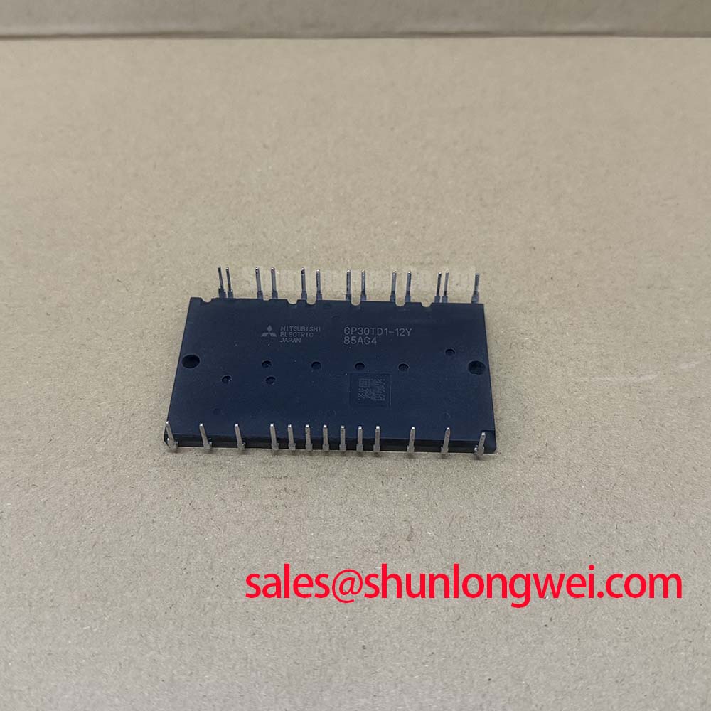
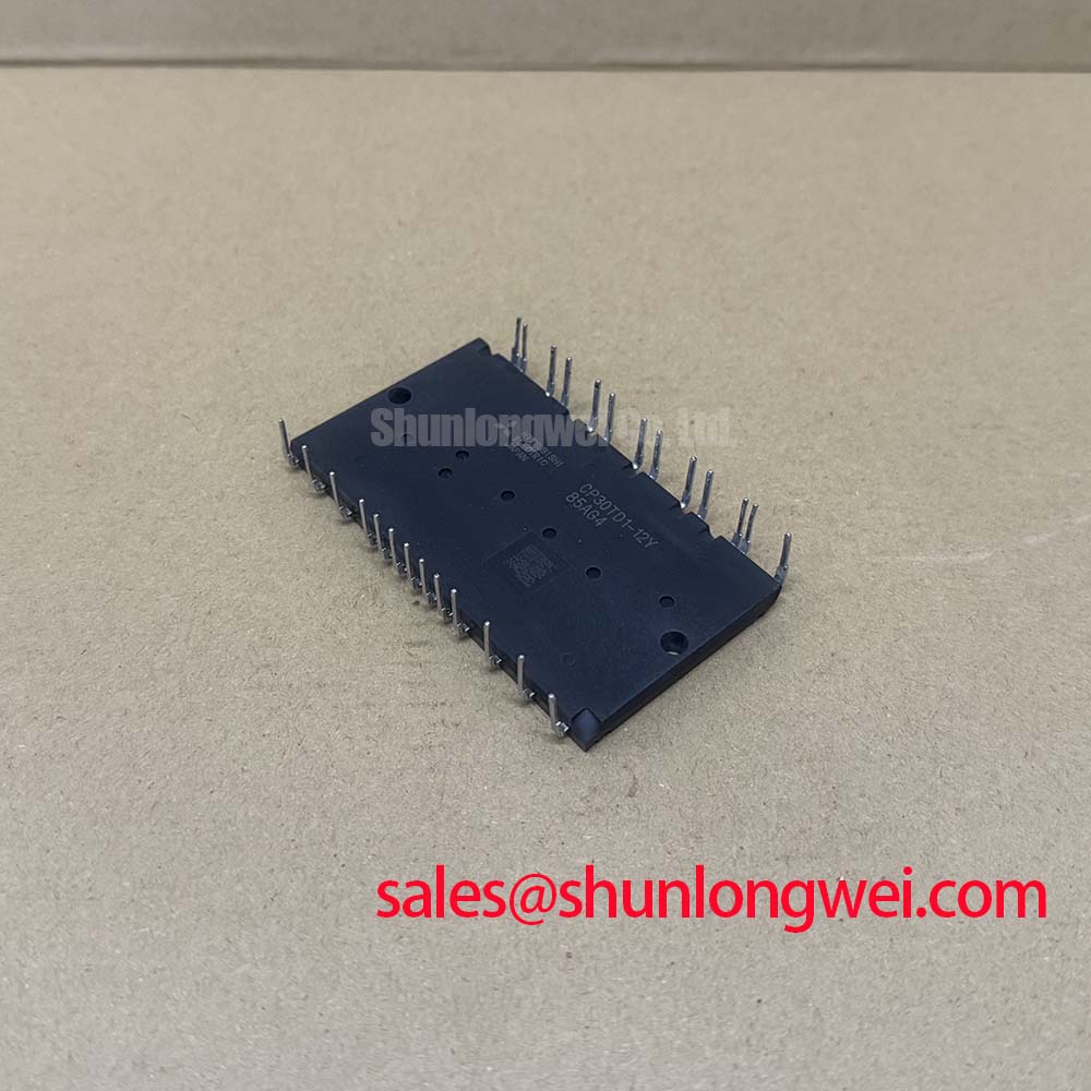
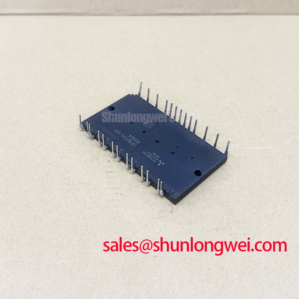
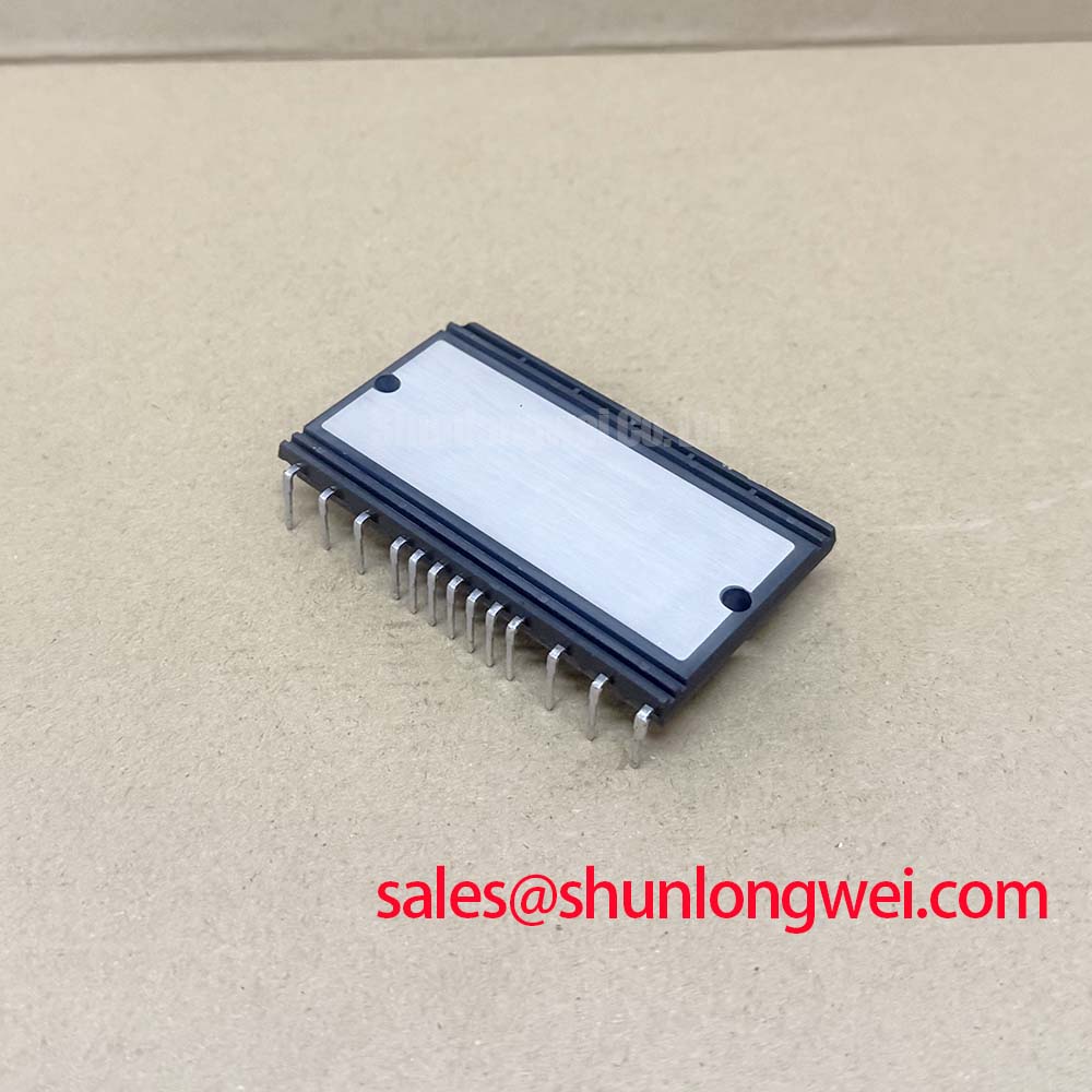
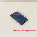
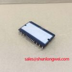
The CP30TD1 12Y is a Mitsubishi Electric IGBT module with an official 600 V collector emitter voltage, 30 A collector current, 2500 Vrms isolation voltage for AC one minute, and an integrated 5 kΩ NTC thermistor at 25°C. These ratings should be checked against the removed unit’s label, connection layout, gate drive arrangement, and inverter schematic before any replacement decision is made.
| Official specification | Value |
|---|---|
| Manufacturer | Mitsubishi Electric |
| Collector emitter voltage VCES | 600 V |
| Collector current IC | 30 A |
| Isolation voltage | 2500 Vrms, AC one minute |
| NTC thermistor resistance at 25°C | 5 kΩ |
| Package type | DIP CIB dual inline package |
Confirm that the measured DC bus, including regenerative and switching events, remains compatible with the module’s official 600 V VCES rating. The static bus reading alone is not enough for a traction inverter repair. Probe the DC link and switch node with equipment suitable for the waveform, then compare peak events during acceleration, deceleration, and motor reversal with the voltage boundary required by the system design.
DC bus headroom is an Engineering Recommendation rather than an additional CP30TD1 12Y factory rating. Busbar routing, DC link capacitor position, motor cable length, snubber condition, and switching behavior can all change the voltage seen at the module. Long motor cables can create reflected voltage events at the motor side, while a poor power loop can increase switching overshoot at the inverter. The system engineer should validate the peak collector emitter waveform under the actual operating load.
No manufacturer supplied FIT, neutron induced single event burnout, or altitude derating figure is stated in the supplied CP30TD1 12Y specifications. For installations above normal terrestrial conditions, altitude and radiation related suitability must therefore be assessed against the equipment level requirements and manufacturer documentation, rather than inferred from the 600 V rating alone. For broader inverter application context, see this Industrial Applications engineering resource.
⚡ Field Alert: Isolate and discharge the DC link before disconnecting module terminals, then apply mounting hardware and thermal interface material according to the equipment manufacturer’s mechanical instructions.
Field Diagnostics & Commissioning: Active Miller Clamp Implementation in CP30TD1 12Y Topologies
After verifying the main terminal arrangement, inspect the gate drive board before powering the inverter. A failed gate resistor, damaged driver output, weak return path, or incorrect gate connector orientation can cause abnormal switching even when the CP30TD1 12Y itself shows no obvious mechanical damage. Compare gate emitter waveforms between phases and against a known good channel where available.
An active Miller clamp is a Design Consideration for topologies where high switching voltage slew rate can couple through gate capacitance and encourage unintended turn on. Whether a clamp circuit, negative gate bias, or another gate control arrangement is appropriate depends on the original driver design and the module’s applicable gate limits. The system integrator should verify the original Mitsubishi Electric documentation and controller board requirements rather than impose a generic gate voltage setting.
During commissioning, inspect the desaturation or short circuit protection path, if the inverter uses one. A protection event should command a controlled shutdown consistent with the existing gate driver architecture. Semiconductor fuse coordination is also system determined: its clearing behavior must be evaluated against the inverter fault energy, bus capacitance, wiring inductance, and protection timing. Do not treat a fuse substitution as proof that the IGBT is protected.
For a different power module option during a documented redesign review, the CM100DY 12E can be examined as a separate device. Terminal layout, current rating, thermal interface, drive conditions, and circuit topology must all be checked; it should not be assumed to be a drop in replacement for CP30TD1 12Y.
Assembly Integrity & Layout Architecture: Implementing Galvanic Gate Drive Isolation, Reinforced for CP30TD1 12Y
The CP30TD1 12Y official isolation specification is 2500 Vrms AC for one minute. This is a module isolation rating and does not establish reinforced insulation status for a complete gate drive system. Gate driver isolators, isolated power supplies, printed circuit board creepage, clearance, enclosure construction, and the applicable equipment standard each require separate verification.
When troubleshooting unexplained gate pulses, inspect the isolation barrier components and the separation between gate control traces and high current switching conductors. A Design Consideration is to keep the gate loop compact and its return path controlled, because common mode switching disturbances can enter poorly routed control wiring. Oscilloscope measurements should be made with an appropriate isolated or differential measurement method to avoid creating an unsafe ground reference or misleading waveform.
The supplied information does not specify a reinforced isolation voltage or common mode transient immunity value. Requirements such as reinforced barriers and transient immunity must be set by the system safety design and verified using the selected gate driver documentation. Mitsubishi Electric’s DIPIPM™ bootstrap circuit design note offers relevant reference principles for reviewing floating drive supply behavior, although the original CP30TD1 12Y circuit requirements remain controlling.
In assemblies with a rectifier or complementary power stage, technicians can review the associated topology and device ratings separately. The CM50DY 28H is a related power module listing that may be relevant to a documented circuit level evaluation, subject to full electrical and mechanical verification.
Transient Dynamics & Electrical Design: Thermal Time Constants and Peak Junction on CP30TD1 12Y
Start thermal assessment with the physical stack. Remove old residue from the mounting interface, inspect the heatsink for flatness and corrosion, and confirm that the module seats evenly before tightening hardware. Uneven clamp force or contaminated thermal interface material can raise case temperature and make a normal electrical load appear to be a semiconductor fault.
The supplied CP30TD1 12Y data identifies the integrated 5 kΩ NTC at 25°C, which can support temperature monitoring when the host controller is designed to interpret it. The NTC reading should be compared with the original controller’s expected temperature conversion and with a measured case condition during controlled operation. A thermistor reading alone does not directly establish junction temperature.
Peak junction estimation requires the manufacturer’s transient thermal impedance information, actual pulse current, switching loss, conduction loss, duty cycle, heatsink response, and ambient conditions. Those thermal impedance curves and allowable junction temperature limits are not included in the supplied official parameter set. Engineers should use the original module documentation and measured waveforms to evaluate pulsed overload behavior rather than calculate a junction margin from nominal current alone.
For electric material handling and forklift low voltage traction equipment, inspect cooling airflow, fan operation, heatsink contamination, battery cable connections, and motor phase connections before assigning a thermal fault to the IGBT module. Intermittent current imbalance, degraded cooling, gate drive timing issues, and abnormal mechanical load can each contribute to elevated inverter temperature.