


Content last revised on June 30, 2026
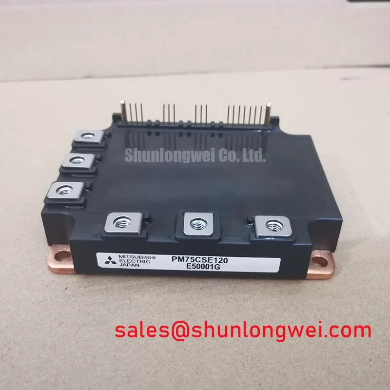
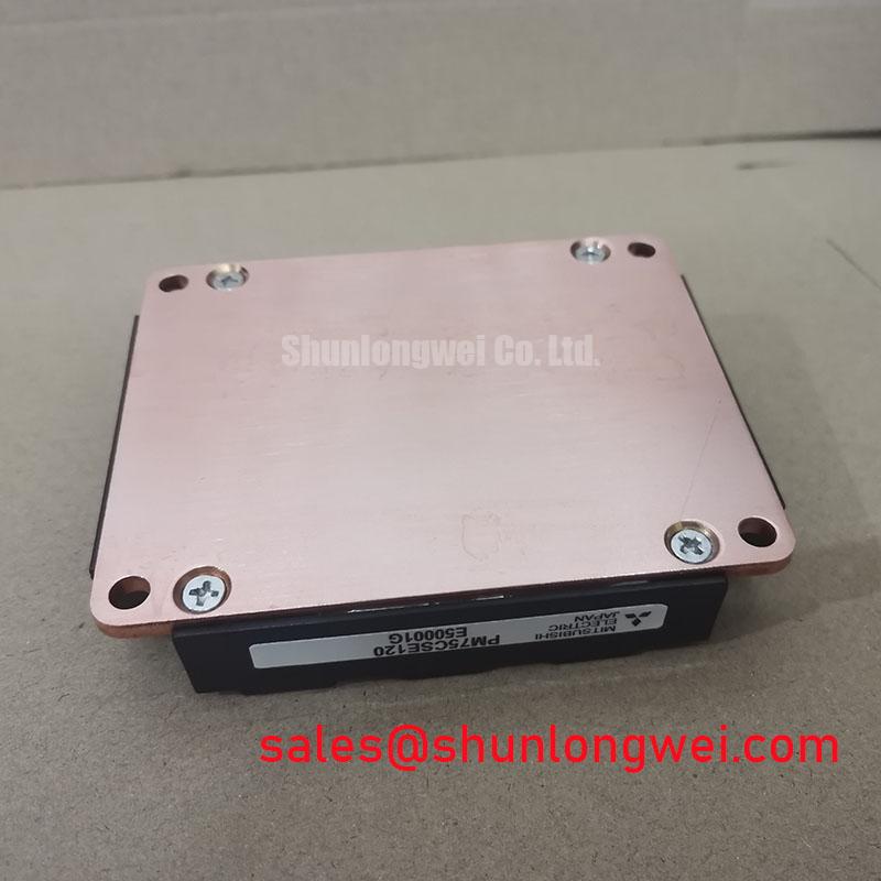
PM75CSE120 Datasheet, Specs & Analysis: A 1200V, 75A IPM for Reliable Motor Drives
An Integrated Power Solution for High-Reliability Inverters
Streamlining Design with Integrated Drive and Protection Features
The Mitsubishi PM75CSE120 is a C-Series Intelligent Power Module (IPM) that streamlines inverter design by integrating drive and protection functions, delivering enhanced system reliability in a single module. This device integrates six IGBTs in a three-phase bridge configuration, along with optimized gate drivers and critical protection circuits. With core specifications of 1200V | 75A | V_CE(sat) 2.7V (max), it offers a robust foundation for power conversion systems. Key engineering benefits include a vastly simplified gate drive circuit and integrated, hardware-based protection against destructive events. This IPM effectively answers the engineering challenge of implementing robust fault management by incorporating short-circuit, over-temperature, and under-voltage detection, which reports faults via a dedicated signal pin for immediate system action. For motor drives up to 37kW requiring robust, built-in protection, the PM75CSE120 offers a highly integrated and reliable solution.
Key Parameter Overview
A Specification Breakdown for System Integration and Fault Management
The electrical characteristics of the PM75CSE120 are tailored for industrial motor control and power conversion applications. The parameters below are specified at Tj = 25°C unless otherwise noted. This table is grouped by function to facilitate efficient review for system design.
| Parameter | Symbol | Conditions | Value | Unit |
|---|---|---|---|---|
| Absolute Maximum Ratings | ||||
| Collector-Emitter Voltage | V_CES | V_GE = 0V | 1200 | V |
| Collector Current (DC) | I_C | Tc = 25°C | 75 | A |
| Collector Power Dissipation | P_C | Tc = 25°C, Per Chip | 347 | W |
| Operating Junction Temperature | T_j | -20 to +150 | °C | |
| Inverter Part Electrical Characteristics | ||||
| Collector-Emitter Saturation Voltage | V_CE(sat) | I_C = 75A, V_GE = 15V, Tj = 25°C | 2.2 (Typ) / 2.7 (Max) | V |
| Forward Voltage (FWDi) | V_ECF | -I_C = 75A, V_GE = 0V, Tj = 25°C | 2.2 (Typ) / 2.7 (Max) | V |
| Control Part Characteristics | ||||
| Control Supply Voltage | V_D | Applied between V_UP1-V_UPC, V_VP1-V_VPC, V_WP1-V_WPC, V_N1-V_NC | 15 (Typ) / 20 (Max) | V |
| Control Supply Under-Voltage Protection Trip Level | V_DUV | Tj = 25°C | 11.5 - 13.5 | V |
| Short Circuit Protection Trip Level | I_C(sc) | V_D = 15V, Tj = 25°C | 150 (Typ) | A |
| Thermal Characteristics | ||||
| Thermal Resistance (Junction to Case, IGBT) | R_th(j-c)Q | Per Module | 0.36 | °C/W |
Download the PM75CSE120 datasheet for detailed specifications and performance curves.
Application Scenarios & Value
System-Level Benefits in Industrial Automation and Power Control
The PM75CSE120 is engineered for demanding applications where reliability and operational uptime are paramount. Its primary use case is in 3-phase Variable Frequency Drives (VFDs) and AC servo drives for industrial automation, robotics, and machine tools. What is the primary benefit of its integrated design? It significantly reduces system complexity and potential points of failure.
Consider the engineering challenge of protecting a 30kW motor drive for a high-inertia industrial conveyor system from a sudden motor stall or winding short. A discrete solution would require a complex external circuit to sense overcurrent, communicate with the gate drivers, and initiate a shutdown, all within microseconds. The PM75CSE120 solves this internally. Its integrated short-circuit protection provides a hardware-level defense that detects the fault and initiates a controlled shutdown faster and more reliably than most external solutions. This prevents catastrophic module failure, protects the load, and simplifies the overall system design, directly contributing to a lower total cost of ownership. The integration of these features offers a more robust path to simplified and reliable power design compared to using discrete components. While the PM75CSE120 is well-suited for applications in this power range, for systems demanding lower output power, the related PM50CSE120 offers a 50A rating, and for higher power needs, the PM100CSE120 provides a 100A capability within a similar package footprint.
Frequently Asked Questions
Engineering Questions on Implementation and Reliability
What is the function of the 'FO' (Fault Output) pin on the PM75CSE120?
The FO pin is an open-collector output that serves as a critical communication link to the host microcontroller. It signals a fault condition, such as a short-circuit, over-temperature, or control supply under-voltage event. This allows the system controller to take immediate and safe action, like disabling the PWM input signals and alerting an operator, which is essential for building reliable Servo Drive and VFD systems.
How does the integrated under-voltage (UV) protection improve system robustness?
The under-voltage lockout (UVLO) protection monitors the module's internal +15V control supply. If this voltage drops below a safe operating threshold, the UVLO circuit automatically shuts down the IGBTs and signals a fault. This crucial safety feature prevents the IGBTs from being driven with insufficient gate voltage, a condition that could lead to operation in the linear region, causing excessive conduction losses, rapid overheating, and potential device destruction.
Technical Deep Dive
Inside the IPM: A Look at Integrated Protection and Drive Circuitry
The core value of the PM75CSE120 Intelligent Power Module from Mitsubishi lies in the synergy between its power switches and the co-packaged control intelligence. The integrated gate drive circuit is not a generic driver; it is specifically matched to the switching characteristics of the internal 1200V IGBTs. This optimization ensures controlled turn-on and turn-off behavior, managing di/dt and dv/dt to balance switching losses and EMI generation without requiring extensive external gate resistor tuning. This tight coupling is fundamental to achieving both high performance and system reliability.
A key integrated feature is the short-circuit (SC) protection. Unlike solutions that rely solely on external monitoring, the PM75CSE120 uses an internal sensing method to detect current levels exceeding the safe threshold (typically 150A). Upon detection, it doesn't just cut the gate signal; it initiates a "soft" shutdown. This controlled turn-off process prevents large voltage overshoots caused by stray inductance in the power circuit, mitigating one of the common causes of catastrophic failures. To draw an analogy, viewing this IPM is like comparing a complete engine with an integrated ECU to a bare engine block. The integrated driver and protection circuits act as the ECU, constantly monitoring vital parameters and intervening instantly to prevent damage, a level of protection that would require a complex and costly external system to replicate for discrete IGBTs.
Application Vignette
Enhancing Reliability in a 30kW Variable Frequency Drive (VFD)
The Challenge: A VFD designed for a high-inertia industrial fan is susceptible to sudden load changes and potential motor winding faults. These events can trigger destructive overcurrent conditions that can destroy power semiconductors in microseconds. The engineering task is to design a protection circuit that is not only fast enough to prevent damage but is also immune to the significant electrical noise present in high-power inverter environments.
The Integrated Solution: By specifying the PM75CSE120, the design team leverages a hardware-based defense mechanism. When a motor fault induces a short circuit, the IPM's internal circuitry detects the collector current rapidly exceeding its trip level. It bypasses the system's main controller to immediately initiate a soft turn-off of the affected IGBTs, while simultaneously asserting the FO (Fault Output) pin to notify the controller of the event.
The Engineering Benefit: This sub-microsecond, hardware-level response is significantly faster than a purely software-based monitoring loop, providing robust protection that is crucial for system longevity. The design team is thereby relieved of the intricate task of selecting, laying out, and tuning a discrete protection circuit, which accelerates the time-to-market. This allows engineers to focus on higher-level tasks, such as optimizing the Pulse Width Modulation (PWM) control algorithm and system thermal management, confident that a validated protection scheme is already in place. The result is a more reliable, compact, and cost-effective VFD.
A Strategic Approach to System Reliability
Integrating the PM75CSE120 into a power system represents a strategic decision to prioritize reliability and reduce design complexity. By abstracting the gate drive and protection functions into a single, validated component, engineering teams can mitigate common design risks associated with noise susceptibility and component interaction. This module-based approach allows for a more predictable development cycle and a more robust end product, aligning with the industry-wide demand for power electronics that offer higher operational uptime and enhanced safety margins in the field.