


Content last revised on March 22, 2026
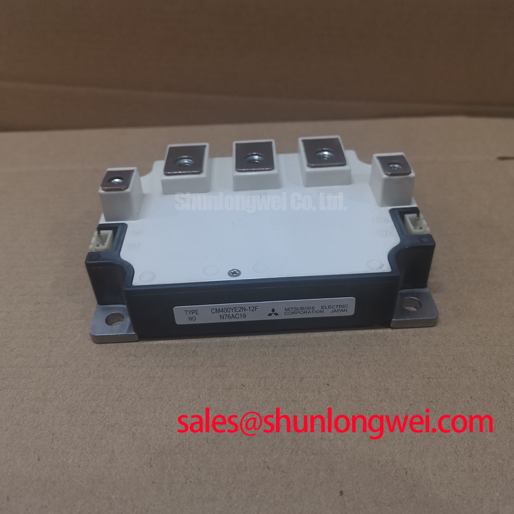
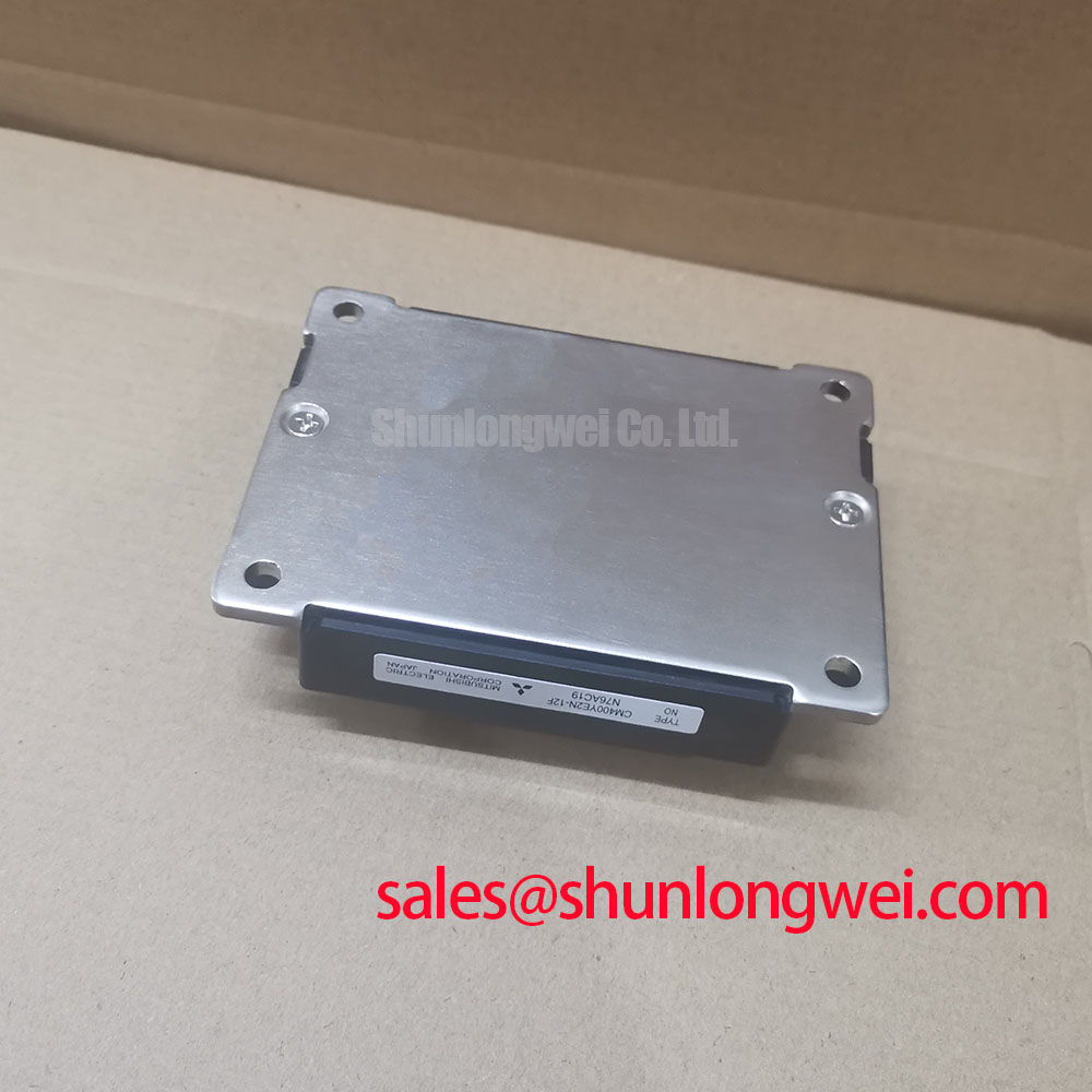
Mitsubishi CM400YE2N-12F | Robust 1200V/400A Single IGBT for High-Power Chopper Applications
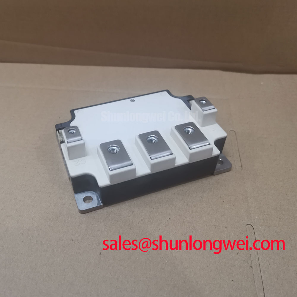
The Mitsubishi CM400YE2N-12F is a high-performance N-channel IGBT module engineered for demanding, high-power switching applications. As a single-switch (chopper) module, it provides a streamlined, robust solution for designers who require precise control over a single power path, eliminating the complexity and potential compromises of using a dual-module configuration. This module is built on a foundation of proven Mitsubishi Electric power semiconductor technology, delivering an optimal balance of efficiency, reliability, and thermal performance.
- High Current Capability: Rated for 400A (DC), providing ample capacity for heavy industrial loads.
- Robust Voltage Rating: 1200V collector-emitter voltage ensures a wide safety margin in 400V/480V AC line applications.
- Low Conduction Losses: Features Mitsubishi's 4th generation CSTBT™ (Carrier Stored Trench-gate Bipolar Transistor) technology, achieving a low VCE(sat) of 2.7V (max).
- Optimized for Single-Switch Topologies: Ideal for brake choppers, high-power DC-DC converters, boost circuits, and welding power supplies.
Key Parameter Overview
For engineers requiring quick access to critical data, the following table summarizes the core performance specifications of the CM400YE2N-12F. For a comprehensive list of all parameters and characteristic curves, you can download the official datasheet here.
| Parameter | Value |
|---|---|
| Collector-Emitter Voltage (V_CES) | 1200 V |
| Collector Current (I_C) @ Tc=25°C | 400 A |
| Collector-Emitter Saturation Voltage (V_CE(sat)) @ Ic=400A | 2.7 V (Max) |
| Short-Circuit Withstand Time (t_sc) | 10 µs |
| Thermal Resistance, Junction-to-Case (R_th(j-c)) per IGBT | 0.083 °C/W (Max) |
Technical Deep Dive: The Engineering Edge of CSTBT™ Technology
The performance of the CM400YE2N-12F is fundamentally rooted in Mitsubishi's advanced Mitsubishi CSTBT™ silicon design. Unlike standard trench IGBTs, this technology incorporates a carrier storage layer beneath the N+ collector region. This innovation significantly enhances conductivity modulation during the on-state.
For the design engineer, this translates directly into a lower Collector-Emitter Saturation Voltage (VCE(sat)), even at high current densities. The immediate benefit is a substantial reduction in conduction losses (P_cond = VCE(sat) * Ic), which is the dominant loss factor in many industrial applications. This superior efficiency simplifies thermal management, allowing for smaller heatsinks or increased power output within the same thermal budget. It's a critical advantage in compact, power-dense system designs.
Where the CM400YE2N-12F Excels: Application-Specific Value
The single-switch topology of this IGBT module makes it a superior choice for specific applications where a half-bridge or six-pack configuration would be inefficient overkill. Its design and ratings provide targeted solutions for common engineering challenges.
- Brake Choppers in VFDs: In high-inertia motor control systems, regenerative energy during deceleration can cause a dangerous DC bus overvoltage. The CM400YE2N-12F serves as the ideal switching element in a brake chopper circuit, reliably shunting this excess energy into a braking resistor. Its high current rating and robust Safe Operating Area (SOA) ensure it can handle the demanding energy pulses from large industrial motors.
- High-Power DC-DC Converters: For applications like large-scale battery chargers, UPS systems, and boost converters for renewable energy, this module provides the core switching component. Its low conduction loss is paramount for maximizing system efficiency, a key metric in power conversion.
- Industrial Welding Power Supplies: The module's ability to handle high peak currents and its excellent thermal stability make it a workhorse for modern welding power supplies. It provides the precise, high-frequency switching needed to control the welding arc, ensuring consistent weld quality.
Strategic Selection: Single IGBT vs. Half-Bridge Modules
Engineers designing chopper circuits occasionally consider using one half of a dual IGBT module. However, selecting a dedicated single-switch module like the CM400YE2N-12F offers distinct advantages. The internal layout is optimized for a single die, providing a more direct and efficient thermal path from the silicon junction to the case. This targeted thermal design often leads to better reliability and longevity under heavy cycling loads. Furthermore, a dedicated single module simplifies the PCB layout by eliminating unused terminals and the need to manage floating, unused components, leading to a cleaner and more robust final design. For help in understanding the thermal dynamics, our guide on why thermal resistance matters provides key insights.
Engineer's FAQ for the CM400YE2N-12F
1. What is the recommended gate drive voltage?
For optimal performance and to ensure robust noise immunity, a gate voltage of +15V for turn-on is standard. For turn-off, a negative gate voltage (e.g., -8V to -15V) is highly recommended. This provides a strong "off" state, preventing parasitic turn-on caused by dV/dt transients, which is a common failure mode in noisy industrial environments. For more detailed guidance, explore our 5 practical tips for robust gate drive design.
2. Can these modules be paralleled for higher current?
Yes, the CM400YE2N-12F can be used in parallel, but it requires careful engineering. To ensure effective current sharing, it is critical to use modules from the same production batch for closely matched VCE(sat) characteristics. A symmetrical power and gate drive layout is essential to minimize stray inductance imbalances, and each module must have its own dedicated gate resistor to suppress potential oscillations. For complex paralleling designs, it is always best to contact our technical team for support.