

Content last revised on September 22, 2026
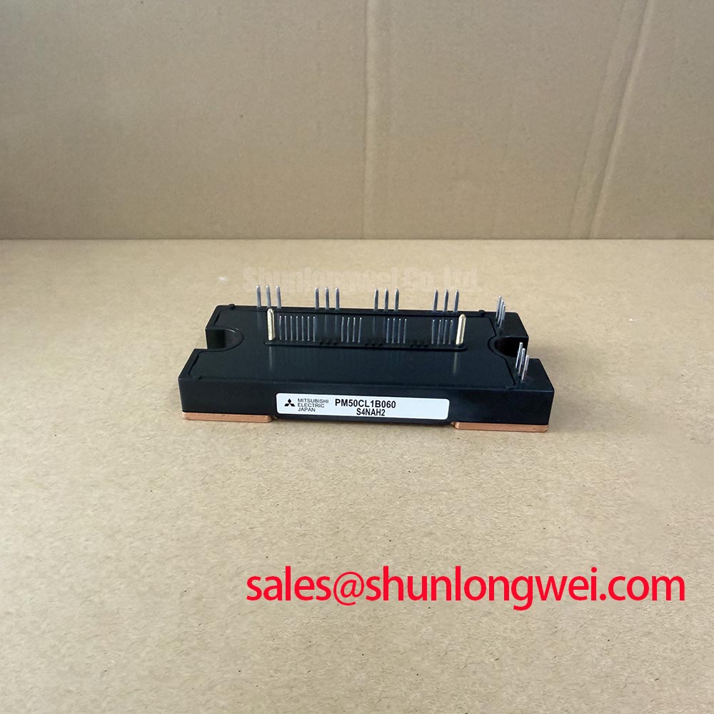
PM50CL1B060 Product Identification and Replacement Checks
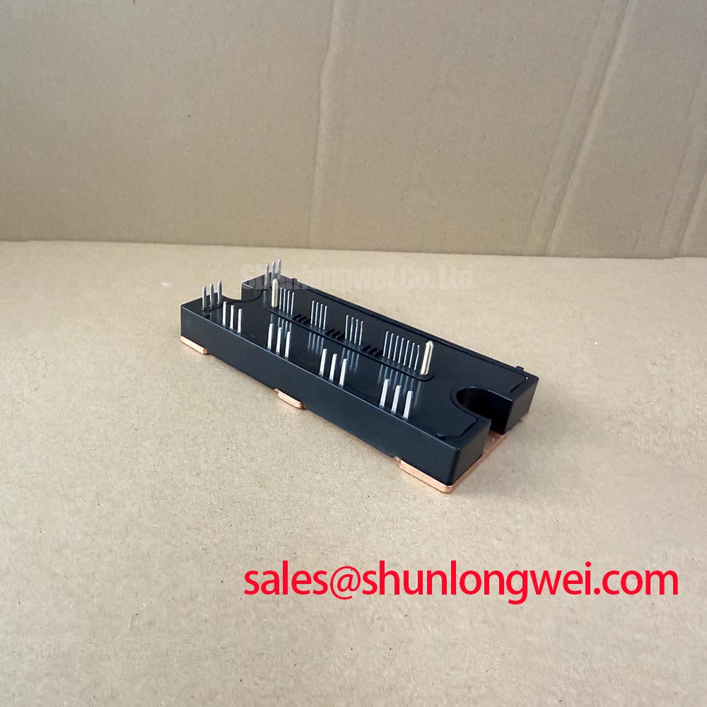
Before fitting the PM50CL1B060, isolate the inverter DC link, confirm that stored energy has discharged, and compare terminal identification and cold-state diode-mode readings with the original removed module and the equipment circuit diagram.
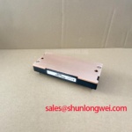
The PM50CL1B060 is a Mitsubishi Electric IPM Module rated at 600 V and 50 A under its official product specification. For incoming inspection, these three identity points should be checked together: the full part marking, the 600 V voltage class, and the 50 A current class. A replacement decision should also account for the original inverter topology, gate-driver interface, bus voltage, mounting plane, cooling arrangement, and protection logic.
| Product Identification | Official Specification |
|---|---|
| Part number | PM50CL1B060 |
| Manufacturer | Mitsubishi Electric |
| Product category | IPM Module |
| Rated voltage | 600 V |
| Rated current | 50 A |
In forklift traction inverters and electric material-handling drive systems, this voltage and current class is commonly evaluated as part of a motor-control power stage. The final suitability remains system-dependent. Engineers should confirm the original equipment documentation, switching operating points, cooling path, controller fault strategy, and the condition of the motor cable before commissioning a replacement module.
💡 Bench Tip: Use ESD-safe handling, keep the module disconnected from the active gate driver during cold testing, and record readings from a known-good phase leg when one is available for comparison.
Field Diagnostics & Commissioning: High dv/dt Cross-Conduction Shoot-Through in PM50CL1B060 Topologies
When a PM50CL1B060 is installed in a bridge topology, an abnormal DC-link current event during switching should not be assigned to one cause without measurement. Cross-conduction can arise when the complementary device in a phase leg receives an unintended gate disturbance during a rapid collector-voltage transition. Gate-loop inductance, shared return impedance, driver output behavior, control timing, probe connection method, and the condition of surrounding passive components can all influence what is seen at the gate terminal.
The practical starting point is to inspect the failure evidence before applying power. Check for discoloration around busbar joints, loose terminal hardware, cracked PCB solder joints, damaged gate-drive connectors, and signs of heat at the DC-link capacitor connections. With the inverter unpowered, compare the gate-drive wiring path of each phase. A phase that differs visibly from the others deserves attention, but physical similarity alone does not prove electrical symmetry.
During controlled commissioning, measure the gate-to-reference waveform and phase-node behavior using an appropriate isolated measurement method. Observe whether an apparent unwanted turn-on coincides with a high rate of collector-voltage change, an unexpected gate rise, or a control-command timing issue. Where the gate-drive architecture supports it, an active Miller clamp is a Design Consideration for holding an inactive gate close to its intended off-state reference during fast switching transitions. Whether such a clamp is appropriate must be verified against the existing driver design and the original module interface.
Negative gate bias is also a Design Consideration, rather than an assumed requirement for this specific IPM module. The required gate-drive range must be verified from the original system documentation and the applicable Mitsubishi Electric technical data. Introducing a changed bias arrangement without validating driver limits, isolation capability, start-up behavior, and fault shutdown behavior can create a different failure mode rather than resolving the original problem.
Minimize the physical area enclosed by each gate-drive loop to suppress inductive disturbance during turn-off and phase-node transitions. This should be assessed alongside the DC-link layout because busbar stray inductance can contribute to voltage overshoot and ringing. The system engineer should validate peak voltage and gate behavior against the actual DC-link operating condition during switching tests. For broader gate-driver signal-path principles, see Precision Gate Drive Design.
In systems using regenerative braking, a traction motor can return energy toward the DC link during deceleration. The braking chopper, braking resistor, control logic, and DC-link capacitors must be evaluated as a complete energy-management path. A rising DC-link voltage during braking may reflect inadequate energy absorption, an inactive chopper command, a wiring fault, or a measurement issue. It should not automatically be interpreted as a defect in the PM50CL1B060.
Preventing Spurious Faults: PCB Gate Loop Layout Symmetry Guidelines for PM50CL1B060
Gate-loop symmetry matters because a phase leg does not switch under ideal schematic conditions. The main current return path can develop voltage during load current changes, and a gate driver that shares part of that return path may see an altered local reference. This can appear as false gate movement, uneven switching behavior, nuisance desaturation-related activity in systems that use such protection, or intermittent controller faults.
A Design Consideration is to keep the gate-driver reference path separate from the main high-current emitter or power-return route wherever the module terminal arrangement and original driver architecture provide a dedicated reference connection. The objective is to prevent the gate-control reference from inheriting voltage disturbance produced by the power loop. The actual terminal function must be confirmed from the equipment documentation and module connection information; it should never be inferred solely from terminal position or naming conventions used on a different module family.
When inspecting a repaired traction inverter PCB, look for unequal trace lengths, altered jumper wires, corroded connector pins, and return paths rerouted during an earlier repair. A gate resistor that has changed value from the original board population, a cracked isolation slot, or a replacement driver component with different propagation behavior can affect the switching relationship between phase legs. These checks are especially important where a fault occurs only after vibration, thermal cycling, or high-current acceleration.
High-side gate-drive supply integrity also deserves direct measurement. If the system uses a bootstrap supply, capacitor selection is a Design Consideration based on the required gate charge, the driver’s quiescent current, leakage paths, switching period, operating duty cycle, and permitted supply-voltage variation. The original design must provide enough stored charge for the actual high-side on-time and switching sequence. Engineers should examine the high-side supply waveform during the longest expected commanded interval, rather than assuming a capacitor is adequate from its physical size.
A brownout or unstable high-side supply may present as irregular switching, a loss of commanded torque, or a protection event, but these symptoms can also originate in control supply regulation, logic interlocks, communication faults, or motor wiring. Compare the affected phase with the known operating channels while retaining the same probe location and reference method. Consistent testing conditions make waveform comparison useful; mixed test references often produce misleading apparent differences.
Where the same industrial cabinet contains an upstream rectifier or other power-stage component, its behavior can influence DC-link quality and inverter diagnostics. The CM100DY-12E is a separate power-module product that may be reviewed objectively when assessing related rectification or power-conversion sections, subject to the original circuit requirements and electrical ratings.
PM50CL1B060 Thermal-Electrical Optimization: Optocoupler vs Digital Coreless Transformer Practical Tuning
Isolation in the gate-drive chain should be evaluated as a system barrier, not as a label attached to a single component. Optocoupler-based and digital coreless-transformer-based driver approaches have different timing, common-mode behavior, supply requirements, and fault-response characteristics. Neither approach can be selected or altered responsibly without reviewing the original control board, power-stage switching environment, gate-drive supply structure, and required isolation coordination.
For the PM50CL1B060, the official supplied product identity establishes the 600 V, 50 A IPM class. It does not by itself establish a particular external driver isolation rating, reinforced insulation classification, or common-mode transient immunity level. Those properties belong to the selected gate-driver and system insulation design and must be verified from their respective documentation. A replacement controller board or isolated-driver modification should therefore be assessed with the relevant component datasheets and the equipment safety requirements.
Common-mode switching activity can couple into isolated control paths through parasitic capacitance, grounding arrangement, cabling, and PCB geometry. A Design Consideration is to maintain clear separation between high-energy switching nodes and low-level gate-control or feedback paths. The required clearance, creepage, and insulation coordination are determined by the system voltage, pollution environment, enclosure design, applicable standards, and installation conditions. These must be reviewed by the responsible equipment designer rather than set from a generic module replacement rule.
Thermal work should begin with the mounting interface. Remove old thermal compound carefully without damaging the module baseplate or heatsink surface. Check the heatsink for flatness, embedded debris, oxidation, and uneven contact marks. Apply thermal interface material in accordance with the equipment manufacturer’s assembly method and tighten mounting hardware in the specified sequence and torque. If the original assembly uses a clamping plate, spring hardware, or a double-sided cooling arrangement, preserve the established load distribution rather than substituting an improvised fastening method.
⚠️ Field Alert: Do not energize the inverter after replacing a power module until every power terminal and gate-drive connection has been checked against the original wiring reference.
For a braking chopper or high-power braking resistor circuit, inspect the resistor terminals, thermal cutout path, contactor status, and the chopper command signal before blaming the inverter module for DC-link overvoltage behavior. A degraded heatsink interface can also alter the apparent operating margin during repeated lift, travel, and regenerative deceleration cycles. Use measured case temperature, cooling airflow or coolant condition, and operating waveform evidence to guide the diagnosis.
Mitsubishi Electric publishes power-semiconductor technology information through its Power Semiconductors and High-Power Modules resource and its Global Semiconductor Device Technologies resource. These references are useful when confirming manufacturer terminology and reviewing the broader product-technology context alongside the exact equipment documentation.
Field Diagnostics & Commissioning: Static and Dynamic Current Distribution in PM50CL1B060 Topologies
Parallel power paths and multi-device arrangements require separate examination of static current distribution and dynamic switching distribution. At steady state, current division is influenced by device conduction behavior, temperature, busbar resistance, cooling uniformity, and connection resistance. During transitions, gate-loop impedance, driver timing, power-loop inductance, and layout geometry become dominant influences. A repair technician should avoid treating these two conditions as the same problem.
The positive temperature tendency of IGBT conduction voltage is commonly considered when engineers assess steady-state sharing in appropriate operating regions. This is an Engineering Consideration, not a guarantee that any arbitrary parallel arrangement will balance automatically. The current-sharing behavior of a finished assembly depends on the complete thermal and electrical environment. For this reason, a system that originally used parallel modules should retain matched topology, comparable conductor geometry, and the intended cooling arrangement unless the responsible design authority has validated a change.
Begin static checks with power removed. Inspect whether parallel current paths have equal conductor cross-sections, comparable joint condition, and consistent contact pressure. Examine busbars for discoloration or mechanical distortion and verify that sensing leads have not been moved onto a noisy power return. If a current sensor is involved, confirm its reference supply, zero point, signal cable integrity, and controller input before reaching a device-level conclusion.
For dynamic checks, compare corresponding gate and collector-emitter waveforms using the same measurement setup across each path. A difference in turn-on or turn-off timing may be associated with driver propagation variation, unequal gate components, a changed routing path, poor connector contact, or measurement-induced error. The appropriate response is to isolate and test each possibility, then validate the repaired circuit under controlled load. Avoid changing several variables at once because that obscures the source of improvement or regression.
If a higher-current power-module family is being considered during an engineering review, the CM300DXDX1-24A can be referenced as a separate product for factual comparison. It should not be treated as a direct replacement for the PM50CL1B060 without confirming package compatibility, circuit topology, driver interface, voltage class, current requirement, protection coordination, mechanical mounting, and thermal design.
For forklift low-voltage traction repairs, commissioning should progress from unpowered checks to controlled low-energy validation and then to monitored operation under the equipment’s approved service procedure. Confirm motor phase continuity, insulation condition, contactor function, DC-link behavior, encoder or resolver feedback where applicable, and controller fault records. The PM50CL1B060 can then be evaluated within the actual inverter system rather than in isolation from the electrical conditions that determine its operation.