Content last revised on September 27, 2026
Assembly Integrity and Junction-to-Case Thermal Response for PM150RLB060
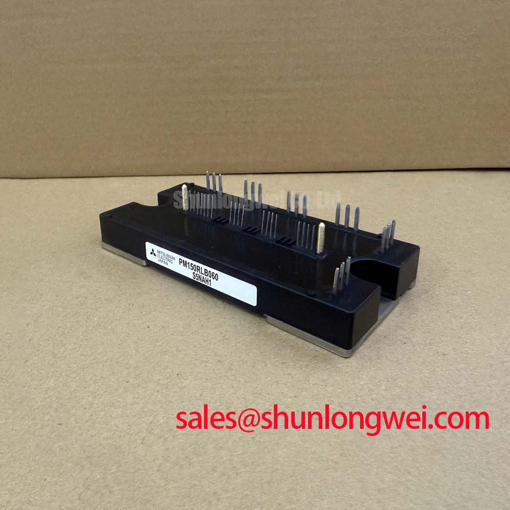
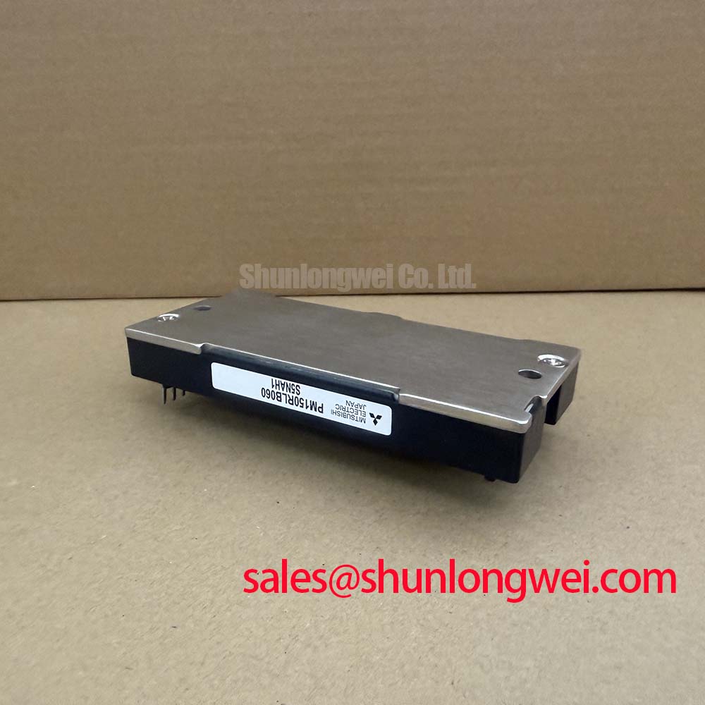
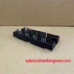
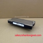
With the drive isolated and its DC link discharged, check the installed module marking and photograph the power and control connections before disconnecting the PM150RLB060. Mitsubishi Electric identifies this part as an IPM module rated at 600 V and 150 A (Official Specifications). Those ratings establish a starting boundary for repair evaluation; they do not establish that an existing drive’s bus voltage, overload profile, mounting arrangement, or control board is compatible.
A heavy-duty variable-frequency AC motor drive can impose short, demanding current pulses during acceleration or load changes. Before evaluating the PM150RLB060 for that duty, obtain the applicable Mitsubishi Electric documentation and the drive’s recorded operating profile. The 150 A rating is an Official Specification, but it is not, by itself, a permissible pulsed-overload schedule. That assessment also needs the specified temperature conditions, loss characteristics, thermal limits, and cooling arrangement.
As a Design Consideration, transient junction temperature depends on both the heat generated during a pulse and how quickly heat reaches the case and heatsink. A multi-RC thermal model can represent that changing response, provided its parameters come from applicable device data rather than an assumed curve for a similar-looking module. Engineers can combine measured or documented switching and conduction losses with the actual pulse sequence, then compare the estimated peak junction temperature with the manufacturer’s stated limit. Where the required thermal data is unavailable, a calculated peak margin should not be presented as a verified property of this part.
Start the physical inspection at the mounting interface. Check the heatsink for contamination, uneven contact marks, blocked airflow, and signs that thermal material has dried or migrated. Review the enclosure’s temperature records alongside drive loading: a rising heatsink temperature under comparable duty may warrant inspection of the fan path, interface, and nearby heat sources. It does not identify a single failed component. For broader context on device losses and thermal behavior, The Ultimate IGBT Knowledge Base is useful background; product-specific limits still require the applicable manufacturer documentation.
Layout matters to the thermal assessment as well. Keep cooling passages clear after reassembly, and verify that adjacent conductors and barriers retain the clearances required by the original equipment design. Do not infer a clearance dimension from the module’s voltage rating alone. Mitsubishi Electric’s power semiconductor information provides manufacturer context, while the drive drawings and relevant device documentation govern the installation being serviced.
DC-Link Capacitor Layout and Switching-Loop Control for PM150RLB060
Trace the DC-link path before moving busbars or capacitors. In a motor-drive inverter, the capacitor bank supplies rapidly changing current to the power stage; a long or asymmetric connection can increase switching-loop inductance and the voltage overshoot seen during turn-off. The 600 V Official Specification is a device voltage rating, not permission to operate the DC link at that value while disregarding switching transients. As a Design Consideration, keep the outgoing and return current paths close together, then measure peak voltage at the relevant power terminals under representative switching conditions.
A compact, symmetric busbar arrangement is a layout principle, not a universal inductance target for the PM150RLB060. The acceptable geometry depends on the existing enclosure, insulation scheme, capacitor placement, switching behavior, and measured overshoot. If a snubber is present, confirm its connection and condition against the drive schematic before changing its capacitance. Snubber selection must be validated for the system’s waveform and energy demand; a capacitor value cannot be established from the module’s 600 V and 150 A ratings alone.
Unexpected faults during switching also call for inspection of the control path. Compare driver-supply behavior, command signals, and fault indications with a known-good drive or the original service documentation. Common-mode transients can disturb signals crossing an optocoupler or digital isolator if the board layout and selected isolation components do not tolerate the measured disturbance. Their immunity is a property to verify in the control-board design, not a specification implied by the IPM label.
Where the drive uses a bootstrap supply for a high-side driver, check whether its voltage remains within the control circuit’s documented operating range through the actual switching sequence. Bootstrap-capacitor evaluation depends on the driver’s consumption, switching pattern, and applicable gate-drive requirements; first verify that this is the supply architecture used by the equipment. Likewise, inspect the gate-drive return routing for avoidable shared impedance before attributing oscillation to the module. Use the original terminal documentation rather than assuming that this part exposes a separate Kelvin-emitter connection.
In the surrounding power path, CM100DY-12E is a separate Mitsubishi Electric module that may appear in engineering comparisons of inverter-stage components. Its connection or role in a particular drive must be established from that drive’s schematic; it should not be treated as a documented companion to the PM150RLB060. Mitsubishi Electric’s semiconductor device resources offer manufacturer context for checking device families and documentation.
Circuit Protection and Reflected-Voltage Checks for PM150RLB060
At the motor terminals, long cables can behave as transmission lines rather than simple wires during fast inverter voltage transitions. Depending on cable length, impedance, termination, and edge rate, reflected waves can raise the voltage seen at the motor above the incident pulse. A doubling of the incident voltage is a possible limiting case under particular mismatch conditions, not an established measurement for every drive fitted with a PM150RLB060. Inspect the installed cable route and motor connection before deciding whether reflected voltage is relevant to a reported insulation or fault event.
For a repeatable check, record the operating state, probe location, and measurement setup, then compare waveforms at the inverter output and motor terminals using suitably rated instruments and the equipment’s safety procedure. An apparent spike may reflect a real terminal transient or a measurement artifact, so probe connection and bandwidth matter. If the waveform is repeatable, assess the cable and motor requirements before evaluating an output choke or dv/dt filter. Filter selection belongs to the drive system design and needs verification against its switching behavior and operating current.
On the DC-link side, turn-off overshoot depends on current change and the inductance of the commutation path. Keep this mechanism separate from reflections on the motor cable: they occur at different locations and may need different corrective work. Review busbar joints, capacitor connections, driver waveforms, and any existing suppression components before adjusting protection settings. A nuisance trip is a symptom to investigate, not proof of excessive bus inductance, an isolator fault, or a defective IPM.
For a maintenance replacement, compare the installed part number, terminal arrangement, mounting interface, drive-control connections, and manufacturer ratings against the equipment documentation. CM300DXDX1-24A is a different module that can be examined in a parts review, but its identity does not establish interchangeability with the PM150RLB060. Do not approve a substitution solely because both parts appear in a power-module catalogue.
Baseplate Contact and Mounting Checks for PM150RLB060
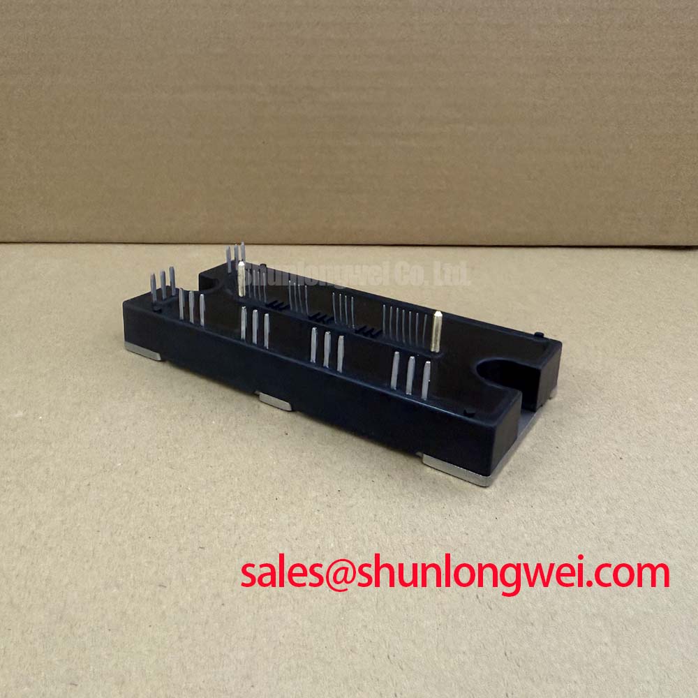
Before mounting the PM150RLB060, inspect the heatsink contact face and the module’s mating surface for debris, damage, and uneven witness marks. Check flatness and mounting requirements against the applicable installation instructions. Baseplate curvature and thermal-interface behavior cannot be judged reliably by sight alone, and neither the required compound thickness nor screw torque can be inferred from the Mitsubishi IPM Module package description.
As a Design Consideration, apply thermal interface material consistently so that the contact path is not interrupted by visible gaps or contamination. An excessively uneven application can make thermal behavior harder to reproduce after a repair. Seat the module according to the specified fastening sequence and torque in the relevant manufacturer or equipment instructions, rather than adopting a generic fastener value. Confirm that tightening does not disturb nearby busbar alignment or place strain on control connections.
Maintenance Note: Isolate the drive and verify that the DC link is discharged before touching the module, its mounting hardware, or connected cables.
After reassembly, review terminal-tightening records, restore the specified cooling path, and monitor heatsink temperature under a documented operating condition. Include heatsink cleaning, airflow checks, and inspection of the thermal interface in the equipment’s maintenance plan; set the interval from site conditions and the equipment manufacturer’s instructions, not an assumed service life for the module. Where low temperatures or humidity create a risk of condensation, inspect the enclosure and follow the drive’s start-up procedure before energizing it. If temperatures or fault indications differ from the pre-repair record, revisit mounting contact, airflow, electrical connections, and measured switching behavior before assigning the cause to the PM150RLB060.