Content last revised on September 25, 2026
Field Diagnostics & Commissioning: Differential Control-Input Loop Routing in PS11032-Y2 Topologies
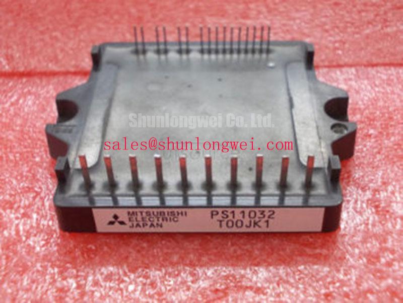
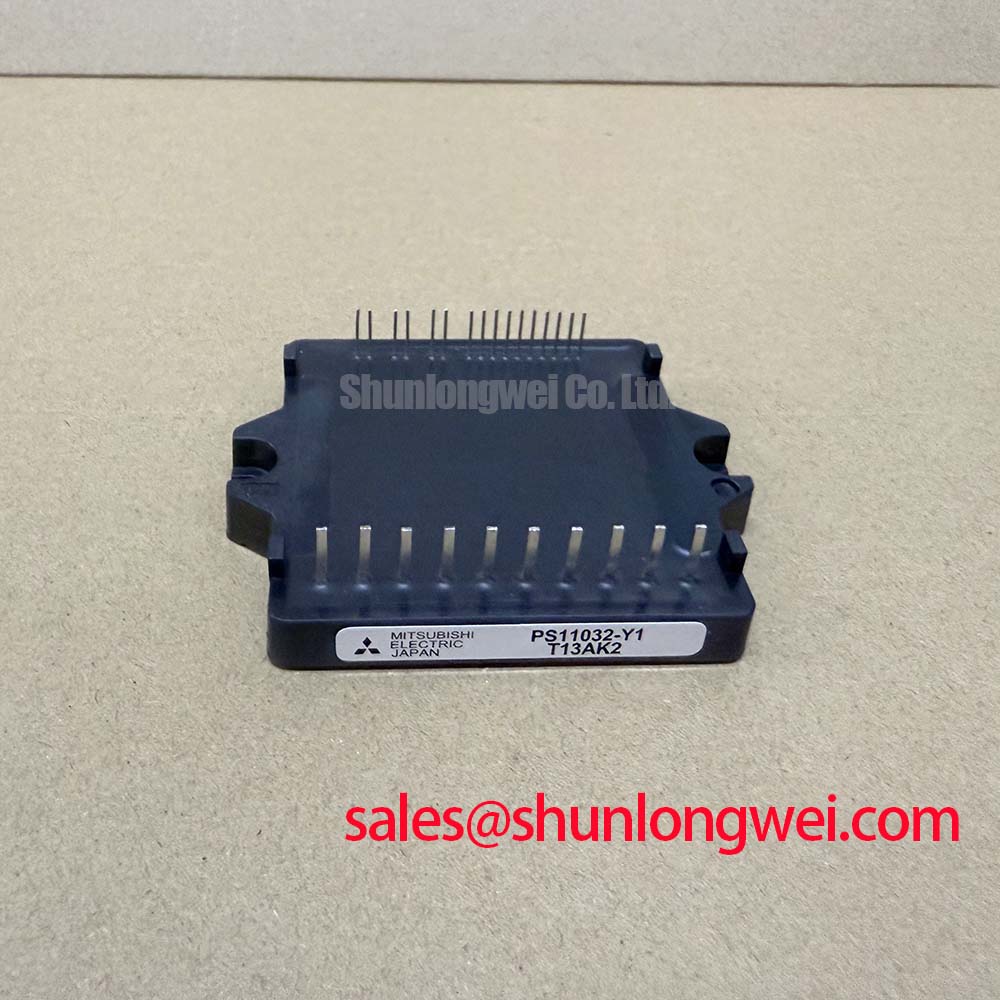
With the DC bus isolated, begin by checking the PS11032-Y2’s package condition, terminal security, and cold-state impedance against a known-good reference before reconnecting the drive. Confirm the original equipment documentation and nameplate limits before applying power. The available manufacturer data identifies the Mitsubishi Electric PS11032-Y2 as a DIP-IPM / Mini DIPIPM with an official rated voltage of 1200.0 V and an official rated current of 15.0 A. These ratings identify the component class, but they do not replace the system designer’s switching, thermal, isolation, and protection verification.
| Parameter | Available specification | Engineering meaning |
|---|---|---|
| Manufacturer | Mitsubishi Electric | Verify the original equipment documentation and module pinout before replacement |
| Product type | DIP-IPM / Mini DIPIPM | Integrated power module format for compact drive electronics |
| Rated voltage | 1200.0 V | Official specification; switching overshoot and bus conditions require separate system validation |
| Rated current | 15.0 A | Official specification; usable current depends on temperature, switching conditions, and cooling |
During a failed-drive inspection, first record the wiring position of every control, power, and auxiliary terminal before removal. Do not assume that a visually similar DIP-IPM has the same control assignment. The system integrator should verify the required supply voltage, logic thresholds, enable behavior, fault feedback, and dead-time requirements from the original module documentation.
For commissioning, measure the module control-input waveform and switching-node behavior at accessible terminals rather than relying only on the controller output. The control-signal loop should be short, direct, and separated from high-current switching paths. The control return should be routed independently from the main emitter current path where the circuit topology provides that connection. This reduces the possibility that shared copper impedance will introduce unwanted feedback into the control signal. If the oscilloscope shows ringing, uneven switching behavior, or a different waveform between low-current and loaded operation, inspect the return routing, connector contacts, and local bypass arrangement before changing control-circuit components.
Use a differential probe suitable for the expected common-mode voltage and confirm probe lead placement. A long ground lead can create an apparent oscillation that is not present at the module terminal. Compare the suspect phase with a known-good phase under the same operating condition. A mismatch may indicate parasitic coupling, inadequate control return routing, or a control-board fault, so the replacement decision should follow the measurement rather than a single resistance reading.
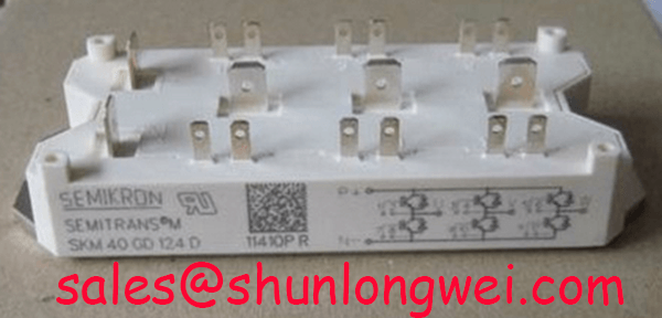
When evaluating a compatible device for a repair bill of materials, engineers may also review the 7MBR15SA120 as a separate device for objective pinout, rating, and mechanical comparison. It should not be treated as a drop-in replacement until the complete electrical and mechanical interface has been verified.
Assembly Integrity & Layout Architecture: Implementing Desaturation Detection for PS11032-Y2
Desaturation protection, short-circuit response, and soft turn-off behavior are system-level functions that must be confirmed from the applicable Mitsubishi Electric documentation and the host inverter design. The supplied product data confirms the 1200.0 V and 15.0 A ratings, but it does not establish a universal short-circuit response time, SCSOA boundary, two-stage protection sequence, or desaturation threshold for every implementation.
In the field, inspect the protection path from the power-stage sensing node to the gate-driver controller. Check for damaged isolation components, contaminated circuit-board surfaces, loose connectors, and incorrect routing near the switching node. A protection circuit that reacts correctly during a bench test may behave differently when cable inductance, motor capacitance, or regenerative energy is present. Designers should verify the complete turn-off waveform and peak voltage during controlled switching tests, with the DC-link condition and load state documented.
Switching frequency and ambient temperature directly affect the available thermal margin. The requested 2 kHz to 16 kHz range should be treated as an evaluation range, not as an official operating guarantee for this model. Confirm conduction loss, switching loss, heatsink performance, airflow, and enclosure temperature at the actual duty cycle. A compact robotic articulator or light automation axis may have short acceleration pulses followed by low-load travel, making the measured duty profile more useful than a nominal frequency alone.
Field Alert: Disconnect the DC bus and verify the discharge condition before removing control or power wiring, because residual energy can damage the module and injure personnel.
PS11032-Y2 Thermal-Electrical Optimization: Dynamic Power Loss Dissipation and Multi-R Practical Tuning
Thermal diagnosis should begin with the mechanical path: inspect the mounting surface, fastener condition, heatsink flatness, interface material, and airflow direction. The 15.0 A rating is an official device parameter, not a universal continuous-current value under every switching frequency or ambient condition. Designers should determine the operating current from the junction temperature limit, case temperature, switching profile, cooling system, and the manufacturer’s thermal data.
For pulsed overload investigation, log the load current, bus voltage, switching frequency, case temperature, and pulse duration at the same time. A short overload can produce a different thermal response from a steady current even when the average current appears similar. A multi-RC thermal model can help estimate transient junction behavior when its resistance and time-constant values are taken from an authoritative module datasheet or validated thermal test. Without those source values, a calculated junction temperature would be speculative.
Inspect the semiconductor fast-fuse coordination separately from the module rating. Fuse clearing behavior, cable inductance, and fault energy determine whether the protection system limits destructive current before the power stage is overstressed. An I²t comparison can be used as an engineering calculation only when the fuse curve, fault waveform, and module short-circuit capability are known. It should not be inferred from the 1200.0 V or 15.0 A label alone.
Control and switching behavior also require measured evidence. For an integrated DIP-IPM, internal gate resistance, Miller behavior, reverse-transfer capacitance, and protection circuitry should not be assumed to be externally adjustable. Verify the control-input timing, switching-node overshoot, current slope, and any documented protection-status signals with suitable probes during the intended load sequence. Minimize the high-current commutation loop and verify peak voltage during operation.
Field Diagnostics & Commissioning: Common-Mode Transient Immunity in PS11032-Y2 Topologies
Do not assign an isolation voltage or common-mode transient immunity value to the PS11032-Y2 unless it is confirmed in the applicable official documentation. The supplied product information does not establish a reinforced isolation rating above 5 kV or a CMTI rating above 100 kV per microsecond. Those values must not be used as design assumptions.
For a robotic axis or automation inverter, inspect the isolation barrier, connector spacing, board contamination, and routing between control and power domains. Creepage and clearance are layout and insulation-system requirements determined by working voltage, pollution environment, material group, altitude, and the applicable safety standard. Verify the finished assembly against the required standard rather than treating the module’s 1200.0 V rating as an insulation-distance specification.
During commissioning, monitor the isolated control supply, fault feedback, control-input waveform, and switching-node behavior while the motor cable and load are connected. A false trigger may arise from common-mode coupling, supply disturbance, grounding arrangement, probe error, or an incorrectly timed protection signal. Compare the event with the controller command and the phase-current waveform. The Mitsubishi Electric Power Semiconductors and High-Power Modules resource is an appropriate reference point for reviewing manufacturer documentation and device-family information.
Where negative off-bias drive is being evaluated by the system designer, the application principles described in Evolution of Negative Off-Bias Gate Drive Circuits can be reviewed alongside the driver manufacturer’s specifications. The final bias level, isolation arrangement, active-clamp method, and switching limits must be validated on the complete inverter, not inferred from the PS11032-Y2 product label.