
Content last revised on September 10, 2026
Thermal Time Constants (tau_i) and Peak Junction Temperature Margin Calculation
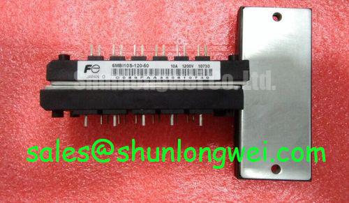
In high-altitude wind turbine pitch and yaw electro-mechanical drive systems, converter modules encounter harsh dynamic power cycling. Pitch actuators regularly execute high-torque bursts during wind gusts, subjecting power switches to heavy pulsed overloads. Operating the Fuji Electric 6MBI10S-120 six-pack IGBT module requires rigorous evaluation of transient thermal impedance Zth(j-c) rather than relying solely on steady-state calculations.
The 6MBI10S-120 features a maximum continuous collector current rating of 10A at TC = 80°C (15A at TC = 25°C), a collector-emitter saturation voltage VCE(sat) of 2.3V typical (2.8V maximum at IC = 10A), and a maximum junction-to-case thermal resistance Rth(j-c) of 1.67 °C/W per IGBT. Under rapid blade-feathering maneuvers, transient current pulses exceed nominal ratings for hundreds of milliseconds. Calculating the peak junction temperature (Tj_peak) during such sub-second peak load events requires decomposing thermal behavior into multi-RC Foster or Cauer equivalent networks:
| Layer / Time Constant (τi) | Equivalent Thermal Resistance (Ri) | Dynamic Response Window | Physical Domain |
|---|---|---|---|
| τ1 (1 ms - 10 ms) | 0.25 °C/W | Sub-cycle microsecond short transients | Silicon Die & Solder Layer |
| τ2 (10 ms - 100 ms) | 0.62 °C/W | Pitch brake release & dynamic stall | DCB Ceramic Substrate (Al2O3) |
| τ3 (100 ms - 1 s) | 0.80 °C/W | Actuator high-torque positioning run | Copper Baseplate Interface |
With a maximum allowable junction temperature of Tj(max) = +150°C and maximum power dissipation PC of 75W per element at TC = 25°C, operational reliability hinges on maintaining dynamic safety margins. In plant operations, peak transient junction temperatures must stay below 125°C under worst-case ambient nacelle conditions (Tnacelle = 55°C). For detailed field testing routines, electrical isolation checks, and root-cause failure validation criteria, consult the Field Engineer’s Handbook.
Cosmic Ray Robustness: Voltage Derating Curves across 2000m-4000m Altitudes
Deploying power electronics in elevated wind farms above 3000 meters exposes semiconductor dies to elevated atmospheric neutron flux. Terrestrial neutron radiation increases the risk of Single Event Burnout (SEB) inside high-voltage blocking junctions. While the 6MBI10S-120 provides a rated collector-emitter breakdown voltage (VCES) of 1200V, raw voltage capacity cannot be fully utilized at altitude without strict derating profiles.
Neutron-induced failure in time (FIT) rates escalate exponentially with DC-bus voltage headroom. At sea level, a DC-bus voltage of 800V yields acceptable failure rates; at 3500m, operating the same module at 800V increases catastrophic SEB probability by a factor of ten or more. For high-altitude yaw converters, the DC-link operational ceiling should be derated to 600V–650V DC.
Fast switching transients amplify this hazard due to stray busbar and trace inductance (Lσ). Turn-off voltage overshoot follows the fundamental relation:
ΔVCE = -Lσ · (di/dt)
When switching inductive motor loads at nominal di/dt rates, a 50nH stray loop easily generates overshoots exceeding 150V. If the DC-link voltage sits at 750V, dynamic peaks reach 900V, placing the device inside the vulnerable SEB zone. For high-surge topologies, integration with external snubbers or high-capacity modules like the 2MBI150F-120 half-bridge configuration helps absorb peripheral commutation spikes. In converter sections requiring dynamic overvoltage absorption, engineers often review dedicated clamping implementations referenced in Fuji Electric Brake Chopper IGBT Modules.
Thermal Interface Material (TIM) Thickness Uniformity and Void Minimization
Preventive maintenance inspections in turbine nacelles consistently show that improper thermal mounting causes premature module failure faster than electrical fatigue. The compact footprint of the 6MBI10S-120 requires flat, uniform mounting to the heatsink to maintain its rated thermal characteristics.
Achieving stable thermal transfer requires maintaining thermal interface material (TIM) thickness between 50 μm and 100 μm. Applying excessive paste creates an insulating blanket because thermal grease conductivity (λ ≈ 1 to 3 W/m·K) is orders of magnitude lower than copper baseplates (λ ≈ 390 W/m·K). Conversely, insufficient paste leaves air voids (λ ≈ 0.026 W/m·K), creating localized hot spots beneath the silicon dies.
💡 Pro Tip: Always apply thermal compound using a calibrated 75 μm metal stencil with a cross-hatch pattern rather than manual spreading. When securing the module, tighten the mounting screws progressively using a calibrated torque screwdriver in a two-stage sequence: initially snug to 0.5 N·m, followed by a final cross-pattern torque of 1.5 to 2.0 N·m. This mechanical sequence compensates for baseplate curvature and expels entrapped air bubbles toward the module perimeter.
⚠️ Maintenance Note: During semi-annual turnarounds, inspect the module perimeter for thermal grease dry-out, silicone bleed, or "pump-out" caused by cyclic thermal expansion. If thermal resistance rises or discolored thermal residue appears, clean the heatsink surface with isopropyl alcohol, verify heatsink flatness to within 50 μm across 100 mm, and re-apply fresh paste. For motor drive channels operating at substantially higher power levels, consider checking larger capacity packages such as the 6MBI300U-120.
Common-Mode Transient Immunity (CMTI > 100kV/us) in Harsh Industrial Environments
Nacelle operating environments are electrically noisy, exposed to lightning-induced surges, variable-frequency drive switching noise, and rapid common-mode voltage fluctuations. Gate driving circuitry for the 6MBI10S-120 must maintain high Common-Mode Transient Immunity (CMTI > 100 kV/μs) across its galvanic isolation boundaries.
The internal freewheeling diodes feature a forward voltage drop (VF) of 2.0V typical at IF = 10A. Rapid diode reverse recovery under high di/dt conditions excites parasitic capacitances between the module's internal power traces and its electrically isolated baseplate. The module provides a factory-tested isolation voltage rating (Vis) of AC 2500V for 1 minute. High dv/dt displacement currents across baseplate capacitance (Ciso ≈ 30–60 pF) will inject noise into signal grounds if layout isolation paths are compromised:
Icm = Ciso · (dv/dt)
To eliminate phantom gate triggers caused by ground-bounce displacement currents:
- Kelvin Emitter Separation: Route gate drive signal returns exclusively through auxiliary emitter terminals. Avoid sharing control return paths with main power emitter tracks carrying high switched currents.
- Negative Gate Bias: Utilize active off-state gate biasing (-5V to -8V) alongside the rated positive drive voltage (+15V, within the VGES = ±20V limit) to suppress Miller-current induced turn-on spikes.
- Creepage and Clearance Maintenance: In high-altitude installations (>3000m), air dielectric breakdown strength decreases. Ensure printed circuit boards preserve enlarged creepage distances (≥ 10 mm) or receive conformal coating compliant with IEC 60664-1 to prevent surface tracking under high-humidity and condensation cycles.
Modern inverter architectures incorporate advanced gate control topologies and active clamping techniques, as detailed in industry references such as the Fuji Electric 7th-Gen X-Series IGBT Modules. Establishing rigorous layout practices, stable gate supply voltages, and routine thermal inspections ensures that the 6MBI10S-120 delivers dependable, long-term performance across demanding industrial environments.