

Content last revised on September 20, 2026
PM10RSH120 Thermal-Electrical Optimization: Differential Gate-Source Loop Routing and Practical Tuning
Before fitting a replacement, isolate the drive, compare the module marking with the controller documentation, and check the power terminals and control connector for contamination, heat staining, loose hardware, or mechanical damage.
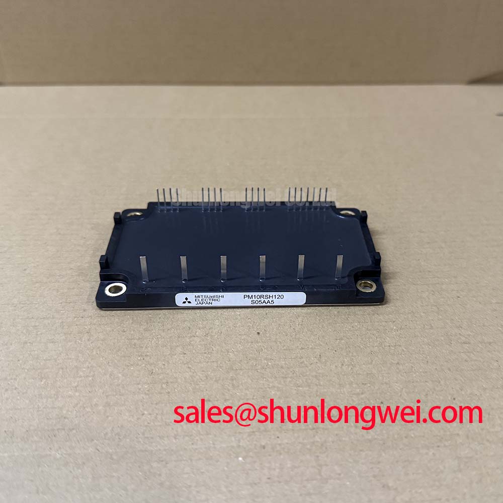
The PM10RSH120 is a Mitsubishi Electric IPM Module with an official 1200.0 V voltage rating and 10.0 A current rating. These are official product identification parameters and should be checked against the original servo drive or motion controller bill of materials before any replacement decision. The module should be evaluated as part of the complete power stage, including the gate-drive interface, DC-link assembly, cooling path, protection circuitry, and motor-cable environment.
| Parameter | Value | Classification |
|---|---|---|
| Product model | PM10RSH120 | Official identification |
| Manufacturer | Mitsubishi Electric | Official identification |
| Rated voltage | 1200.0 V | Official specification |
| Rated current | 10.0 A | Official specification |
| Package category | Mitsubishi IPM Module | Official specification |
For component-family context and manufacturer technology information, consult Mitsubishi Electric Power Semiconductors & High-Power Modules and Mitsubishi Electric Global Semiconductor Device Technologies. These references support system-level evaluation but do not replace verification of the original equipment documentation.
During maintenance of a compact servo amplifier, start by tracing the control connection from the driver board to the PM10RSH120 and identifying whether the original circuit provides a separate low-current gate return path. The pin assignment and internal configuration must be verified from the original drive documentation before modifying any control wiring. A replacement module can have the correct voltage and current class while still requiring an exactly matched connection arrangement within the existing equipment.
Design Consideration: gate-drive stability depends on the physical loop formed by the drive output, the gate connection, the associated return path, and the driver reference. High-current power return conductors can develop transient voltage during switching. If that voltage is shared by a sensitive gate-reference route, the effective command seen by the switching device can be disturbed. This can appear on a scope trace as ringing, inconsistent switching edges, or unwanted gate movement when another switch in the power stage changes state.
Where the original circuit provides distinct power and control return routing, preserve that architecture. Keep the gate-drive path close to its intended return conductor and avoid extending it alongside noisy motor output conductors or DC bus bars. Do not assume that an unused terminal position can serve as an alternate control return. The system integrator should verify the intended terminal functions from the original equipment schematic and the applicable module documentation.
For a high-dynamics CNC axis or robotics servo drive, troubleshooting should begin with comparative measurement rather than changes to component values. Inspect the gate-drive waveforms using the same probe method on a known-good axis where available. Compare command timing, gate behavior, DC-link movement, and motor-current feedback under an equivalent controlled operating condition. A difference may indicate a layout issue, driver-board fault, isolation problem, or measurement-reference error; it should not be treated as proof of a single module-level cause.
When a driver board has been removed for repair, examine soldered connector pins, control cable strain relief, board support hardware, and the separation between control traces and power conductors. Condensation residue and conductive dust near low-level control connections can alter signal behavior without leaving an obvious electrical fault during a static multimeter check.
⚠️ Maintenance Note: After every scheduled shutdown, monitor terminal contact temperature under comparable load and confirm that the cooling airflow path remains clear of dust accumulation.
PM10RSH120 Operational Boundaries: Evaluating Active Miller Clamp Implementation Limits
The official 1200.0 V and 10.0 A ratings establish key equipment-selection boundaries for PM10RSH120, but they do not by themselves define allowable switching frequency, gate-drive voltage, cooling requirement, overload behavior, or protection thresholds in a finished machine. Those operating conditions are determined by the original drive topology, the actual load profile, the thermal assembly, and the controller protection strategy.
Design Consideration: in inverter and servo power stages, a rapid voltage transition at one switching node can couple into an adjacent gate-control circuit. An active Miller clamp, where supported by the original gate driver, is intended to hold the inactive gate at a low impedance relative to its reference during these transitions. Its effectiveness depends on driver implementation, PCB layout, control-return routing, and the switching environment. It should be assessed with switching measurements rather than assumed from the presence of a clamp-capable driver IC.
Negative gate bias is also a system-level design choice. It is not an official PM10RSH120 parameter provided here, and no specific bias value should be inferred for this module. If the existing drive uses a bipolar gate supply, service personnel should confirm rail integrity, driver enable sequencing, isolation-barrier behavior, and gate-reference continuity before installing a replacement. A missing negative rail, damaged bootstrap or isolated supply section, or degraded control connector can create abnormal switching behavior even when the power module is not the initiating fault.
Thermal assessment should focus on measured conditions. Switching losses generally change with switching activity and current waveform, while conduction losses change with load current and junction conditions. In a multi-axis CNC or robotics servo cabinet, acceleration cycles can produce a thermal profile very different from steady holding torque. Engineers should verify heatsink temperature, fan performance, air recirculation, enclosure filter condition, and temperature response during the actual duty cycle used by the machine.
Check for restricted airflow around nearby braking resistors, transformers, and DC-link capacitors. Hot exhaust air recirculating toward the module heatsink can reduce available cooling even when the fan itself still rotates. Where high ambient temperature or condensation risk is present, inspect cabinet seals, heater arrangements if installed by the equipment builder, and the drainage condition around cable entries. These are maintenance checks, not product-specific environmental ratings.
In a power-conversion chain, a device such as FP10R12KE3 can be assessed as a separate related power-stage component when its documented electrical ratings, package, circuit role, and control requirements match the original design. It is not a presumptive substitute for PM10RSH120.
PM10RSH120 Circuit Protection & Reliability: Calibrating Planar Symmetrical Busbar Geometry
Inspect the DC-link path before attributing an overvoltage event to the PM10RSH120. Check the condition of DC-link capacitors, busbar fasteners, insulation barriers, discharge resistors, cable lugs, and the physical distance between the capacitor bank and the power module. Loose or oxidized joints can add impedance and create local heating. A cracked busbar support or displaced insulation sheet can also change the geometry of the current path after vibration or prior service work.
Engineering Calculation: the peak switching voltage in an inductive commutation loop is influenced by the DC-link voltage plus the product of loop inductance and the rate of current change. This relationship explains why reducing loop inductance is important when controlling turn-off overshoot. It does not yield a safe hardware setting without measured current transition data, module switching information, and the original system protection limits.
Design Consideration: closely coupled positive and negative DC bus conductors help minimize loop area and can reduce inductive overshoot. If a planar or laminated busbar arrangement is used in the original drive, preserve conductor order, insulating layers, mounting points, and clearances during repair. Do not add wire extensions or relocate DC-link components without validating peak voltage margins against the DC-link condition during controlled switching tests.
MOV networks and snubber assemblies must be treated as coordinated protection elements rather than independent accessories. An MOV can absorb limited transient energy according to its own documented capability, while a snubber network can shape a particular switching transient depending on its placement and circuit values. The original equipment schematic determines where these parts belong and how they interact with the DC-link. A visibly intact MOV is not evidence of electrical health; its condition should be evaluated using approved service procedures and the equipment documentation.
Maintain creepage and clearance distances established by the equipment manufacturer around high-voltage terminals, busbar supports, and protective covers. Carbonized contamination, metallic dust, excess solder, trapped fastener washers, and moisture paths can compromise insulation coordination. Clean only with methods compatible with the complete assembly, and verify that no cleaning residue remains between live conductors and grounded heatsink structures.
Protection analysis should also include the controller’s current-sensing and fault-latching path. If the drive reports an overcurrent, desaturation, DC bus, or ground-fault event, capture the sequence of status signals where service access permits. A trip can result from the load, cable, encoder feedback interaction, driver supply, sensor path, or switching stage. Replacing the module without recording the event context can leave the original system-level fault unresolved.
For broader device-operation terminology and power semiconductor principles, see The Ultimate IGBT Knowledge Base. The resource is useful for engineering review; the installed equipment schematic remains the controlling reference for service decisions.
PM10RSH120 Thermal-Electrical Optimization: Derating Guidelines and Mismatched Parameter Practical Tuning
Current sharing and dynamic balance become relevant when a power stage contains parallel current paths or multiple switching positions that must operate symmetrically. The PM10RSH120 official current rating is 10.0 A, but no parallel-operation capability, matching tolerance, thermal-derating curve, or switching characterization is stated in the supplied official data. Any parallel or matched-drive evaluation therefore requires the original manufacturer documentation and validation in the finished assembly.
Design Consideration: IGBT conduction characteristics can show a positive temperature coefficient in some operating regions, which can assist steady-state current sharing under appropriately controlled conditions. It does not guarantee balanced sharing in a real drive. Dynamic balance is strongly affected by gate-loop symmetry, control signal timing, parasitic inductance, temperature distribution, and current-path resistance. Engineers should compare measured waveforms and temperatures across equivalent positions instead of assuming uniform behavior from matching part numbers.
When installing the module onto its existing heatsink interface, remove old thermal interface residue carefully and inspect the contact plane for scoring, corrosion, raised burrs, or distortion. Apply the equipment-approved interface material according to the original assembly procedure. Uneven clamping can increase thermal resistance, create local stress, or leave part of the contact area poorly coupled to the heatsink. Fastener order, torque, insulating hardware, and any spring elements must follow the equipment manufacturer’s documented procedure.
Disc springs or pressure hardware, if present in the original assembly, should not be flattened, mixed across positions, or replaced with arbitrary hardware. Their purpose is usually to maintain clamping force through thermal movement and vibration. The required compression condition is assembly-specific and must be verified from the machine documentation rather than estimated from visual appearance.
Preventive maintenance should include periodic cleaning of the heatsink fins, inspection of fan bearings and filters, review of terminal tightness using the equipment specification, and checks for moisture ingress at cabinet openings. During cold starts in humid areas, look for evidence of condensation before energizing the drive. A controlled insulation inspection process, performed under the equipment maker’s safety instructions, can help identify contamination or moisture concerns around high-voltage conductors.
For cross-model evaluation, SKIIP37AC12T4V1 is a separately listed power module that can be reviewed against the original circuit requirements. Voltage class, current capability, package arrangement, control interface, cooling arrangement, and protection architecture must all be checked; it should not be treated as a direct replacement based on a single rating.