
Content last revised on September 17, 2026
Assembly Integrity & Layout Architecture: Implementing Thermal Feedback for PM200CSA060
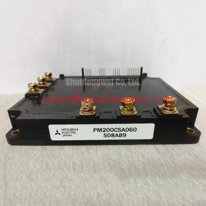
Before reconnecting a stopped power unit, isolate the DC bus, inspect the module terminals and baseplate contact area, then compare the installed nameplate with the required PM200CSA060 rating. This Mitsubishi Electric intelligent power module is officially specified at VCES = 600V and IC = 200A. Its listed isolation withstand capability is 2,500Vrms for one minute under the stated AC test condition. These values establish the electrical identity of the replacement unit; they do not by themselves validate the surrounding driver board, bus capacitors, cooling path, or control logic.
For static conduction assessment, the official collector-emitter saturation-voltage specification is 1.75V typical and 2.63V maximum at IC = 200A and Tj = 125°C. During service investigation, this parameter is most useful as a controlled comparison point rather than a cold multimeter pass-or-fail value. A module operating under comparable current and temperature conditions with an unexpectedly higher conduction drop can indicate that the cooling interface, current path, drive condition, or load balance deserves further inspection.
For parallel current paths, the positive temperature tendency of IGBT conduction behavior can support steady-state current sharing once devices reach thermal equilibrium. That principle does not correct unequal switching behavior. Design Consideration: keep the gate-drive routing symmetrical, return each gate signal through its intended emitter reference, and avoid giving one parallel path a visibly longer or more inductive route than another. Dynamic imbalance is frequently introduced by connection geometry, not by a single rated-current number printed on a module label.
When installing a replacement, remove old residue from the heatsink, inspect the mounting surface for burrs or localized damage, and apply the thermal interface material consistently according to the equipment maintenance procedure. Confirm that power lugs, control connectors, standoffs, and insulating hardware are seated before energizing. Field Alert: Disconnect and verify the DC-link discharge state before handling control or power terminals, because stored bus energy can remain after the machine is switched off.
For an inverter welder or medium-frequency induction-heating supply, evaluate the complete switching leg rather than treating the module as an isolated repair item. Check phase-to-phase wiring, current-feedback connections, thermal-sensor paths, and the mechanical relationship between the module and heatsink. If the existing design includes a front-end rectifier stage, a component such as the CM100DY-12E can be reviewed as a separate topology element, but its electrical and mechanical suitability must be verified against the original schematic and service documentation.
Preventing Spurious Faults: Turn-Off di/dt Induced Vpeak Clamping and Guidelines for PM200CSA060
A nuisance trip or repeated shutdown during load release should be investigated with controlled switching measurements, beginning at the module terminals and DC-link connection points. At turn-off, peak device voltage is influenced by the DC bus plus the inductive contribution created by the commutation loop and the rate of current change. In practical terms, a faster current transition through a longer or poorly coupled current loop raises the overshoot that the 600V device must withstand. The system engineer should verify the actual peak voltage margin during switching tests rather than assigning a universal gate-resistor or bus-inductance value.
Design Consideration: minimize the area enclosed by the DC-link capacitor, power module, and return conductor. Closely coupled planar conductors and short, direct capacitor connections help contain stray inductance and reduce turn-off ringing. A film snubber, where included by the original power-stage design, should be positioned according to the actual high-frequency commutation path instead of merely near the cabinet busbars. Its capacitance, voltage capability, ripple behavior, and connection method must be selected from measured waveform conditions and the system’s switching requirements.
Gate-loop layout needs the same attention. A gate command that appears clean at the driver connector can arrive with ringing at the module if the gate and reference path are physically separated or influenced by power-loop magnetic fields. During commissioning, use probing practices that preserve waveform integrity and compare the gate-emitter signal, collector-emitter voltage, current signal, and fault output in the same event window. Ringing, delayed desaturation response, or inconsistent pulse widths may indicate a layout, driver-supply, probe, or grounding issue; confirm against a known-good channel before replacing additional parts.
The PM200CSA060 provides an official over-current protection trip level of 310A minimum and 400A typical across the stated junction-temperature range of −20°C to 125°C. It also lists a 560A typical short-circuit protection trip level across that same temperature range. These are protection characteristics, not continuous operating targets or externally programmable current settings. Verify how the host equipment interprets the module protection output, including fault latching, restart timing, current-sensor scaling, and any controller-side inhibition logic.
For bootstrap-supplied gate-drive arrangements, the capacitor recharge opportunity and diode recovery behavior should be verified under the real pulse pattern, particularly where extended duty intervals can alter the available drive supply. The Mitsubishi Electric DIPIPM Bootstrap Circuit Design note provides useful general reference material for assessing bootstrap circuit behavior. It should be applied as an engineering reference, with final component values and timing determined by the actual driver architecture and measured operating waveforms.
Preventing Spurious Faults: Transient Thermal Impedance Guidelines for PM200CSA060
When a machine trips only after repeated weld pulses or prolonged heating cycles, first compare the event timing with the heatsink temperature, cooling flow, and commanded load sequence. The PM200CSA060 specifies over-temperature protection at 118°C typical. This is an official protection threshold characteristic, not a substitute for a complete thermal design limit. The temperature seen by the sensing and protection structure can be affected by pulse duration, cooling response, mounting condition, and the distribution of loss within the inverter.
Transient thermal behavior differs from a stabilized cabinet-temperature reading. A short overload can heat the semiconductor junction faster than the heatsink sensor reacts, while a sustained process may reveal restricted airflow, pump degradation, blocked coolant passages, or uneven baseplate contact. Engineering Recommendation: review the equipment’s thermal model as a time-dependent junction-to-case and case-to-heatsink path. The allowed pulse duty, load profile, and restart logic should be established from the original system requirements and verified using measured temperature and switching-loss conditions.
At 200A, the published VCE(sat) limits provide a relevant conduction-loss boundary at the stated 125°C junction condition, but switching loss remains dependent on the external operating point. Gate-drive timing, DC-link voltage, switching frequency, commutation behavior, and load current all influence the thermal result. Do not infer junction temperature from one parameter alone. A thermal investigation is more defensible when it combines controlled waveform capture, cooling-system inspection, and observation of the protection sequence.
For field service, inspect fan direction, coolant circulation where applicable, heatsink contamination, mounting clamp condition, and the condition of temperature-feedback wiring. A fault that appears after reassembly can also arise from a pinched harness, a loose connector, a control-board reference problem, or an altered airflow path. Record the conditions at which protection occurs and compare them with the original machine cycle. This avoids assigning a single cause to a thermal event that may have electrical and mechanical contributors.
Where a redesign team is considering a different semiconductor technology or evaluating high-frequency power-stage behavior, the Wide Bandgap Revolution technical guide offers broader context on GaN and SiC design considerations. That material does not establish a direct replacement path for PM200CSA060; voltage class, current duty, protection interface, mounting arrangement, and controller compatibility still require separate verification.
Field Diagnostics & Commissioning: Regenerative DC-Bus Voltage Surge Dissipation in PM200CSA060 Topologies
During commissioning, monitor the DC-bus voltage whenever the load is decelerated, interrupted, or returned to a lower power command. In inverter welders and induction-heating systems, stored energy in magnetic elements, motion systems, or process loads can return energy to the DC link under certain operating sequences. If the bus rises during those events, inspect the intended energy-management path before attributing the shutdown directly to the PM200CSA060.
Some systems use a braking switch and ballast resistor, while others rely on a controlled regenerative path, capacitor bank, or supply-side energy handling method. The module’s 600V collector-emitter rating defines an official device limit, but braking-device voltage rating, pulse current capability, resistor energy capacity, enclosure temperature, and controller timing remain system-determined. Engineering Recommendation: confirm the original topology, then measure bus behavior during the actual deceleration or process-release event with an appropriately rated measurement arrangement.
Check whether the braking command appears when the bus rises, whether the resistor path is electrically continuous, and whether the relevant control interlocks are active. A missing command can point toward sensing, firmware logic, auxiliary-supply, or interlock conditions. A present command with insufficient bus control can indicate that the energy path, resistor assembly, conductor connections, or operating sequence needs closer evaluation. These observations should be correlated with the measured bus waveform and machine load state.
For repair planning, retain the original protection architecture wherever possible and verify connector orientation, control-input polarity, and phase connection sequence before applying power. A cross-model option such as the CM300DXDX1-24A should only be evaluated through documented comparison of voltage rating, current duty, pin arrangement, isolation requirements, protection behavior, mechanical fit, and driver compatibility. A higher current label alone does not establish an interchangeable installation.
A final controlled energization should begin with the machine’s specified low-risk commissioning procedure. Observe the DC bus, fault indication, gate-drive supply condition, output current feedback, and cooling response before restoring normal duty. This approach gives the repair team evidence that the power stage, protection paths, and regenerative energy handling are operating together as intended.