Content last revised on September 10, 2026
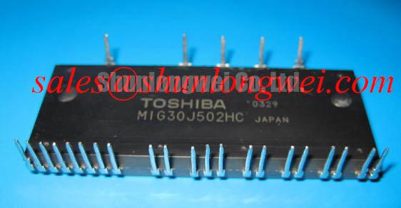
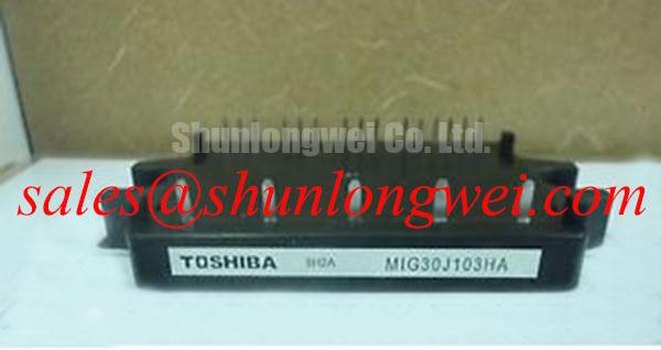
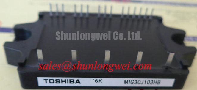
MIG30J103HB Toshiba: 600V 30A Intelligent GTR Module Analysis
The Toshiba MIG30J103HB intelligent module fundamentally simplifies motor control designs by integrating essential drive circuits and robust fault protections directly alongside the power silicon. 600V | 30A | Vce(sat) 2.7V. This architecture delivers simplified circuit design and enhanced fault tolerance. Are external gate drivers required for this device? No, the MIG30J103HB integrates the necessary IGBT drive circuits internally to streamline PCB layout. What is the primary benefit of the MIG30J103HB? It enhances system reliability by integrating drive circuits with comprehensive fault protections. For compact 600V motor drives prioritizing built-in fault tolerance, this 30A intelligent module is the optimal choice.
Key Parameter Overview
Defining the Functional Boundaries of the Intelligent Module
To fully leverage the MIG30J103HB, engineers must understand both its power handling capabilities and its embedded logic boundaries. The functional grouping below outlines the core electrical specifications alongside the active protection features.
| Functional Group | Parameter | Specification |
|---|---|---|
| Power Characteristics | Collector-Emitter Voltage (Vces) | 600V |
| Continuous Collector Current (Ic) | 30A | |
| Saturation Voltage (Vce(sat) Max) | 2.7V | |
| Dynamic Performance | Turn-On Time (Ton) | 2.0 µs |
| Device Architecture | N-Channel Intelligent GTR | |
| Integrated Protections | Overcurrent (OC) | Active Hardware Shutdown |
| Undervoltage Lockout (UVLO) | Active Hardware Shutdown | |
| Overtemperature (OTP) | Active Hardware Shutdown |
Download the MIG30J103HB datasheet for detailed specifications and performance curves.
Application Scenarios & Value
Achieving System-Level Benefits in Motor Control
Engineers often face significant spatial and thermal constraints when designing a Variable Frequency Drive (VFD) for compact industrial equipment. Traditional power stage layouts demand discrete gate drivers, external sensing resistors, and dedicated protection comparators. The MIG30J103HB eliminates these peripheral components. By embedding overcurrent and overtemperature protection directly onto the substrate, the module reacts instantly to motor startup surges or locked-rotor conditions. This rapid intervention prevents the internal silicon from operating outside its Safe Operating Area, thereby drastically increasing the Mean Time Between Failures (MTBF) by circumventing the latent delays typical of MCU-based software protections.
While the MIG30J103HB excels in 30A and 600V scenarios, engineers requiring higher continuous current handling for heavier 600V systems can consider the MIG50J7CSB1W. For cross-evaluating alternative intelligent topologies, the 6MBP30RH060 offers a highly comparable 30A 600V IPM solution. Choosing an integrated approach over discrete assembly is thoroughly explored in our guide on IPM vs discrete IGBT design.
Technical & Design Deep Dive
Decoding the Intelligent GTR Architecture for Superior Reliability
The official designation of the MIG30J103HB is an Intelligent GTR Module. While commonly grouped with standard power modules, this terminology highlights its advanced hybrid nature. It combines a high-performance N-Channel IGBT power stage with logic-level control circuitry. This unified system reliability approach fundamentally changes how engineers route PCB traces, as high-current and sensitive analog feedback lines no longer need to span across the main board.
Think of the integrated Undervoltage Lockout (UVLO) as a safety interlock on an industrial elevator door. It simply prevents the system from operating if the foundational power conditions are dangerously inadequate. If the control voltage dips below a secure threshold, the UVLO halts the 30A output. This preemptive block stops the MIG30J103HB from operating in a linear, highly resistive state, completely avoiding catastrophic thermal runaway.
Furthermore, using an internal gate drive rather than external components is like having an on-board engine control unit (ECU) mapped precisely to the motor, rather than relying on a generic aftermarket controller. It ensures that parasitic inductance between the driver output and the IGBT gate is virtually eliminated. This tight physical coupling guarantees that the 2.0 µs Ton switching transitions are executed flawlessly, strictly controlling switching losses while minimizing unwanted electromagnetic interference (EMI).
Frequently Asked Questions
Addressing Core Engineering Inquiries for the MIG30J103HB
- How does the integrated Undervoltage Lockout (UVLO) in the MIG30J103HB improve system longevity?
The UVLO circuit actively monitors the internal control supply voltage. If the supply drops below the minimum required threshold to fully saturate the gate, it instantly disables the 30A output. This prevents the 600V IGBT die from operating in a high-resistance linear state, eliminating the risk of massive heat generation and sudden component failure. - Can the MIG30J103HB be used to replace standard discrete 600V 30A IGBTs directly?
No. Because the MIG30J103HB is an Intelligent GTR Module, it requires standard low-voltage logic control signals rather than direct high-current gate-emitter driving voltages. Engineers must redesign the interface to utilize its built-in driver circuits and logic inputs.
Contact us to secure your supply chain, verify real-time inventory, or request a quote for this intelligent module for your next power project.