
Content last revised on October 12, 2026
6MBI30FA-060 Thermal-Electrical Optimization: Cold-State Main Terminal Impedance Practical Tuning
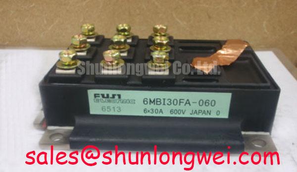
With the DC bus fully isolated, discharge the drive assembly, and record the cold-state resistance and diode-check readings between the identified power terminals before applying any external supply. The 6MBI30FA-060 is a Fuji Electric IGBT module rated at 600.0 V and 30.0 A, with a Fuji Power Module package. These are official specification values for initial replacement screening; they do not replace the terminal diagram and test conditions in the applicable manufacturer documentation.
Use a calibrated digital multimeter with the module disconnected from the gate driver, brake circuit, DC-link capacitor, and motor cable. A resistance reading taken while the module remains connected to the inverter can be dominated by snubber capacitors, gate resistors, current sensors, or parallel semiconductor paths. Mark the terminal positions from the original assembly before probing. Do not infer terminal polarity from physical position alone, because the replacement must match the electrical topology of the drive board.
In diode-check mode, measure the documented antiparallel diode paths in both directions. The forward reading should be treated as a comparative bench value rather than a universal acceptance limit. Compare corresponding phases and, where available, compare the readings with a known-good module tested using the same meter, lead pressure, temperature, and settling time. A display showing conduction in both directions, an unstable reading that does not settle, or a strong imbalance between equivalent paths warrants isolation testing before energization.
Gate leakage screening is best performed with the gate terminals separated from the driver circuit and with the main terminals held at a defined, safe condition. Keep the test voltage within the limits stated by the module documentation and the test instrument. A gate-to-emitter reading that changes after repeated probing may reflect stored charge, contamination, or an external driver path rather than an intrinsic module fault. Discharge the gate in a controlled manner before repeating the measurement.
For a precision stepper or BLDC motor servo actuator, the static check should be followed by a wiring audit. Confirm that each phase output reaches the intended motor terminal, that the DC-link positive and negative paths are not reversed, and that the gate-driver connector cannot be offset by one position. Signal isolation, bootstrap supply paths, and desaturation or overcurrent feedback should be checked separately because a correctly measured power module can still be damaged by an incorrect driver sequence.
As a Design Consideration, keep the power commutation loop short and physically separated from sensitive gate and current-feedback wiring. The system designer should determine creepage, clearance, insulation coordination, and enclosure requirements from the working voltage, pollution environment, applicable safety standard, and board construction. The module’s 600.0 V rating is an official electrical boundary; it is not by itself a complete system insulation or transient-compliance declaration.
When a replacement comparison is required, the 1MBI400L-060 can be reviewed as a related Fuji module reference. It should not be treated as a drop-in substitute without checking topology, pin arrangement, mechanical envelope, thermal interface, gate characteristics, and protection coordination against the original inverter design.
💡 Bench Tip: Use ESD protection and record a cold, unpowered baseline for every equivalent diode and gate path before connecting the replacement to the energized control board.
Transient Dynamics & Electrical Design: High-Speed Semiconductor Fuse I2t Melting on 6MBI30FA-060
Coordinate the semiconductor fuse with the complete fault path rather than selecting protection from the module’s 30.0 A rating alone. A high-speed fuse must interrupt the available DC-link fault current before the semiconductor package and bus structure experience destructive energy, while its total clearing I2t, let-through current, voltage rating, and prospective fault current remain compatible with the equipment.
The engineering review begins with the actual DC-link arrangement. Identify the rectifier, pre-charge circuit, capacitor bank, contactor, braking branch, motor cable, and any parallel inverter sections. The fuse manufacturer’s published melting and clearing data should be compared with the module manufacturer’s short-circuit and surge limits under the relevant pulse duration and operating temperature. These values are system-coordination data, not additional official ratings for the 6MBI30FA-060.
Phase-angle control and line-frequency ripple can change the stress presented to the module. In a controlled rectifier or variable-speed drive, the firing sequence determines how quickly the DC link replenishes after a disturbance. A heavily rippled link can produce repetitive current peaks, while excessive smoothing capacitance can increase the energy available during a hard short. The protection study should therefore use the measured or calculated bus waveform at the intended operating point, including pre-charge behavior and regeneration.
For precision motion equipment, inspect the relationship between the inverter switching pattern and the motor’s acceleration and deceleration profile. Rapid torque commands can create current transients that do not appear during a low-load static test. The gate driver, isolated control channel, fault latch, and fuse must respond as one protection chain. Optical or digital isolation should be evaluated for common-mode transient behavior in the actual layout; a nominal isolation rating does not establish the switching immunity of the assembled drive.
Bootstrap supply design also affects transient control. The high-side supply capacitor must retain adequate gate-drive voltage during the intended high-side conduction interval, while the charging diode and resistor must recover between switching events without creating excessive current spikes. The correct capacitance, diode recovery behavior, charging impedance, and switching frequency are determined by the driver circuit and operating waveform. Verify the supply at the gate pins with an oscilloscope using a measurement arrangement that does not add misleading loop inductance.
RC snubbers can reduce ringing caused by commutation-loop inductance and device capacitance, but their values should be selected from measured overshoot, ringing frequency, resistor pulse capability, and thermal dissipation. A snubber that is too aggressive can increase switching loss and capacitor heating. Place the network close to the switching nodes it is intended to control, and validate the result at the highest practical DC-link voltage and load condition permitted by the test plan.
| Evaluation Item | 6MBI30FA-060 | Related Replacement Review |
|---|---|---|
| Manufacturer | Fuji Electric | Confirm manufacturer and documentation |
| Rated voltage | 600.0 V official specification | Must meet the original circuit requirement |
| Rated current | 30.0 A official specification | Must be assessed with thermal and switching conditions |
| Package | Fuji Power Module | Check mounting and terminal compatibility |
| Protection coordination | System determined | Review fuse I2t and total clearing behavior |
The upstream rectifier or auxiliary power stage may also influence the fault energy and recovery sequence. The 6MBI450U-170 is a separate Fuji module reference that may be considered when mapping a broader converter topology, but its electrical function and ratings must be evaluated independently from the inverter module.
Fuji Electric’s material on RC-IGBT Modules and Brake Chopper IGBT Modules provides useful context for distinguishing switching and braking functions. Those product families should not be assumed to share the same topology, terminal arrangement, or protection requirements as this module.
Field Diagnostics & Commissioning: Eliminating Thermal Grease Pump-Out in 6MBI30FA-060 Topologies
Thermal interface inspection should start with the copper baseplate and heatsink contact surfaces, because uneven contact can create local thermal resistance even when the electrical measurements are normal. Remove the module without scraping across the baseplate, then inspect the heatsink for machining marks, embedded debris, old compound, and visible distortion. Clean both surfaces using a process approved for the materials and the equipment environment.
The interface compound should form a continuous, thin film after tightening rather than a thick reservoir around the mounting points. Film thickness should follow the selected material and the applicable installation instructions; it is not an official electrical rating of the module.
Check the heatsink flatness with appropriate metrology before installation. A concave or twisted heatsink can leave the center or corners lightly loaded, while excessive local pressure can stress the module base. The module should sit naturally on the prepared surface without rocking. Do not use mounting screws to pull a visibly distorted heatsink into position, as this can create uneven mechanical loading and accelerate interface migration during thermal cycling.
Apply the fasteners in a diagonal cross-pattern using a calibrated torque tool and the fastener torque specified by the module documentation or equipment manufacturer. If those instructions are unavailable, the system engineer must determine a suitable value from the fastener size, thread material, washer arrangement, clamp requirement, and module mechanical limits rather than borrowing a value from another package. Recheck the final seating pattern after the compound has spread.
Thermal grease pump-out is often associated with repeated expansion and contraction of dissimilar materials, but the field inspection should also consider fan performance, airflow blockage, heatsink orientation, cabinet vibration, and the thermal duty cycle. Record the temperature at comparable load points and compare phase behavior rather than relying on one surface reading. A thermal imbalance can originate in current sharing, switching loss, airflow, sensor placement, or interface contact.
During commissioning, ramp the DC link and motor command under controlled conditions while observing gate signals, phase current, heatsink temperature, and fault feedback. The purpose is to identify whether thermal rise follows load current, switching activity, regeneration, or mechanical contact quality. For a servo actuator, include acceleration, deceleration, holding, and regenerative events in the test plan because each condition changes the loss distribution.
Layout clearance around the power terminals should allow safe probing, insulation spacing, and service access without routing measurement leads through high-current commutation loops. The designer should minimize parasitic loop area where it can produce turn-off overshoot, then verify peak voltage against the DC-link boundary during switching tests. The thermal interface review can be placed alongside the broader principles discussed in The Advanced Thermal Management Revolution.
Before final enclosure closure, inspect the gate-driver connector, brake resistor wiring, DC-link bus joints, and protective earth path. Confirm that the module mounting hardware has not displaced the board or strained the terminal busbars. If the drive has a regenerative braking chopper, verify that the braking command, resistor temperature monitoring, and overvoltage response operate together under a controlled test load.