


Content last revised on April 16, 2026
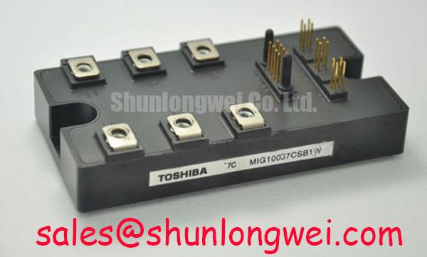
MIG50J7CSB1W: A Deep Dive into the 600V/50A Intelligent Power Module for High-Frequency Drives
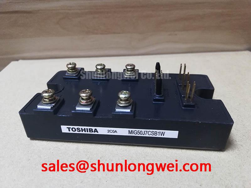
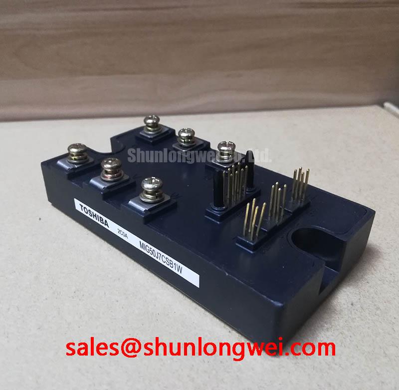
The MIG50J7CSB1W is a high-integration Intelligent Power Module (IPM) designed for demanding three-phase motor control applications. This device encapsulates a 600V | 50A IGBT six-pack with optimized gate drive and protection circuits, engineered to reduce system complexity and enhance operational reliability. Key benefits include minimized switching losses, integrated under-voltage and short-circuit protection, and a design focused on simplifying the thermal management process. By integrating the core power stage with essential protection features, this IPM directly addresses the engineering challenge of creating compact, robust, and efficient Variable Frequency Drive (VFD) systems. For applications requiring a higher current rating while maintaining a similar integrated approach, the MIG75J6CSB1W offers an increased 75A capability.
Application Scenarios & Value
System-Level Benefits in Compact Motor Drives
The MIG50J7CSB1W is engineered for scenarios where space, efficiency, and reliability are critical design constraints. A prime example is in sophisticated servo drives for CNC machinery or robotics. In these systems, engineers face the challenge of delivering precise motor control within a confined enclosure, where poor thermal performance can lead to derating and premature failure. The module's integrated nature, combining IGBTs and freewheeling diodes with drive circuitry, significantly reduces the PCB footprint compared to a discrete component solution. Its specified thermal resistance is a critical parameter that directly facilitates a more predictable and compact heatsink design, ensuring the junction temperatures of the power devices remain within the safe operating area even under high-frequency switching conditions typical of a Servo Drive .
Key Parameter Overview
Decoding the Specs for Efficient Power Conversion
The technical specifications of the MIG50J7CSB1W are tailored for robust performance in inverter stages. The table below highlights the key parameters that directly influence its application suitability. The collector-emitter voltage (Vces) of 600V provides a solid safety margin for systems operating on 200/240V AC lines, while the 50A continuous collector current (Ic) defines its power handling capability.
| Parameter | Value | Conditions |
|---|---|---|
| Collector-Emitter Voltage (Vces) | 600V | Vge = 0V |
| Collector Current (Ic) | 50A | Tc = 25°C |
| Forward Voltage Diode (VECF) | 2.5V (Max) | Iec = 50A, Vge=0V |
| Collector-Emitter Saturation Voltage (Vce(sat)) | 2.7V (Max) | Ic = 50A, Vge=15V |
| Turn-On Time (ton) | 2.0µs (Max) | Ic = 50A |
| Turn-Off Time (toff) | 3.0µs (Max) | Ic = 50A |
| Isolation Voltage (Visol) | 2500V | AC, 1 minute |
Download the MIG50J7CSB1W datasheet for detailed specifications and performance curves.
Industry Insights & Strategic Advantage
Meeting the Demands of Industrial Automation and Electrification
The trend towards Industry 4.0 and widespread electrification places immense pressure on power electronics to be more efficient, compact, and intelligent. The MIG50J7CSB1W is a direct response to this evolution. Its IPM architecture aligns with the need for simplified design cycles and faster time-to-market for equipment like industrial pumps, fans, and conveyor systems. By integrating protection features such as short-circuit (SC) and under-voltage (UV) lock-out, this module offloads complex and critical protection design from the main control board. This not only reduces the bill of materials but also enhances the overall system's robustness, a critical factor in factory environments where electrical noise and voltage fluctuations are common. The integration can be likened to using a pre-certified engine assembly in a car rather than building one from individual pistons and valves; it guarantees a certain level of performance and reliability, allowing engineers to focus on higher-level system control and functionality.
Frequently Asked Questions (FAQ)
What is the primary benefit of the integrated drive and protection circuits in the MIG50J7CSB1W?
The primary benefit is enhanced system reliability and a simplified design process. By co-packaging the IGBTs with their optimized gate drivers and protection features like short-circuit and under-voltage lockout, the module minimizes parasitic inductance and ensures proper device operation, reducing the risk of catastrophic failure that can occur with discrete designs.
How does the Vce(sat) of 2.7V impact system efficiency?
The Collector-Emitter Saturation Voltage, or Vce(sat), is the voltage drop across the IGBT when it is fully turned on. A lower Vce(sat) translates directly to lower conduction losses (Power Loss = Vce(sat) * Ic). While 2.7V is a typical value for this class of device, it is a crucial parameter for calculating total power dissipation and ensuring the thermal design can maintain a safe operating temperature, which is fundamental to overall system efficiency.
What does the 2500V isolation rating signify for system design?
The 2500V (AC, 1 minute) isolation rating confirms that the module's internal circuitry is electrically isolated from its mounting baseplate. This is a critical safety feature, ensuring that high voltage from the power circuit does not leak to the grounded heatsink, protecting both the equipment and personnel. It simplifies meeting safety standards like UL or IEC in the final product design.
Is this module suitable for high-frequency switching applications?
With maximum turn-on and turn-off times of 2.0µs and 3.0µs respectively, the MIG50J7CSB1W is well-suited for applications with PWM frequencies in the range of 5 to 15 kHz, typical for many motor control and UPS (Uninterruptible Power Supply) systems. The switching times are a key factor in determining switching losses, which become more significant as frequency increases.
What is the function of the integrated freewheeling diodes (FWDs)?
The FWDs are essential for any inductive load application, such as a motor. When an IGBT turns off, the energy stored in the motor's inductance must have a path to flow. The FWDs provide this path, preventing a large voltage spike across the IGBT that would otherwise destroy it. The characteristics of these diodes are matched to the IGBTs for optimal performance.
Strategic Considerations for System Design
Integrating the MIG50J7CSB1W offers a strategic pathway to developing more competitive power conversion systems. Its design philosophy prioritizes reliability and engineering efficiency. By abstracting the complexity of the power stage into a single, pre-validated component, engineering teams can reallocate resources from gate drive design and protection tuning to core competencies like control algorithms and user interface development. This approach not only accelerates the product development lifecycle but also results in a more robust and field-reliable end product, reducing total cost of ownership through lower service and warranty expenses.